ATAVRAUTO102 Atmel, ATAVRAUTO102 Datasheet - Page 6
ATAVRAUTO102
Manufacturer Part Number
ATAVRAUTO102
Description
DEBUGGER KIT
Manufacturer
Atmel
Series
AVR®r
Type
Evaluation kitr
Datasheet
1.ATAVRAUTO102.pdf
(18 pages)
Specifications of ATAVRAUTO102
Contents
2 Boards, cable and software
Processor To Be Evaluated
AT90CAN128 and AT90USB1287
Interface Type
USB
For Use With/related Products
AT90CAN128
Lead Free Status / RoHS Status
Lead free / RoHS Compliant
Other names
Q3524911


7720A–AVR–06/07
2.3
2-4
Quick Start
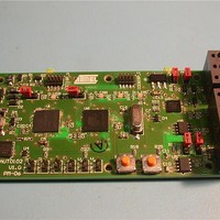
The ATAVRAUTO102 board can be used to analyze up to one CAN and two LIN net-
works. Connect networks (LIN and/or CAN) and plug USB cable.
Figure 2-1. Board connections and default jumpers settings
Note:
Table 2-1. Main Jumpers function
The default configuration allows to use the board with LIN and CAN.
Note:
USB
Jumper
D_WD
MAST
MISO
MOSI
TERM1
TERM2
NISP_U
NISP_C
NRES_U
NRES_C
BOOT_U
BOOT_U
At least one “VBat” should be connected to have the LIN interfaces working.
For more details on ATAVRAUTO102 options, please refer to “Using
ATAVRAUTO102” chapter of the user guide.
Description
Set to disable the LIN transceiver watch dog (default REMOVED).
Set to use the master mode of LIN0 (default SET).
Set to enable the SPI comm between both microcontrollers (default
SET).
Set to enable the CAN termination resistors (default REMOVED)..
Set to enable the reset signal from the LIN transceiver to the
AT90CAN128 (_C) or/and the aT90USB1287 (_U) microcontrollers
(default SET)
Set to reset the AT90CAN128 (_C) or the AT90USB1287 (_U) microcon-
troller (default REMOVED).
Reserved for future use (default REMOVED).
ATAVRAUTO102 User Guide
VBat
VBat
CANH
CANL
LIN0
GND
GND
LIN1
Related parts for ATAVRAUTO102
Image
Part Number
Description
Manufacturer
Datasheet
Request
R


Part Number:
Description:
DEV KIT FOR AVR/AVR32
Manufacturer:
Atmel
Datasheet:

Part Number:
Description:
INTERVAL AND WIPE/WASH WIPER CONTROL IC WITH DELAY
Manufacturer:
ATMEL Corporation
Datasheet:
Part Number:
Description:
Low-Voltage Voice-Switched IC for Hands-Free Operation
Manufacturer:
ATMEL Corporation
Datasheet:
Part Number:
Description:
MONOLITHIC INTEGRATED FEATUREPHONE CIRCUIT
Manufacturer:
ATMEL Corporation
Datasheet:
Part Number:
Description:
AM-FM Receiver IC U4255BM-M
Manufacturer:
ATMEL Corporation
Datasheet:
Part Number:
Description:
Monolithic Integrated Feature Phone Circuit
Manufacturer:
ATMEL Corporation
Datasheet:
Part Number:
Description:
Multistandard Video-IF and Quasi Parallel Sound Processing
Manufacturer:
ATMEL Corporation
Datasheet:
Part Number:
Description:
High-performance EE PLD
Manufacturer:
ATMEL Corporation
Datasheet:
Part Number:
Description:
8-bit Flash Microcontroller
Manufacturer:
ATMEL Corporation
Datasheet:
Part Number:
Description:
2-Wire Serial EEPROM
Manufacturer:
ATMEL Corporation
Datasheet: