DK-SI-2SGX90N Altera, DK-SI-2SGX90N Datasheet - Page 24
DK-SI-2SGX90N
Manufacturer Part Number
DK-SI-2SGX90N
Description
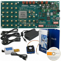
SI KIT W/SII GX EP2SGX90N
Manufacturer
Altera
Series
Stratix® IIr
Type
DSPr
Datasheet
1.DK-SI-2SGX90N.pdf
(38 pages)
Specifications of DK-SI-2SGX90N
Contents
Dev Board, Quartus®II Web Edition, Cables, Accessories, Reference Designs and Demos
For Use With/related Products
Stratix ll GX 2SGX90N
Lead Free Status / RoHS Status
Lead free / RoHS Compliant
Other names
544-1724
Available stocks
Company
Part Number
Manufacturer
Quantity
Price


Test the Transceiver Performance Using Pre-Defined Designs
2–16
Transceiver Signal Integrity Development Kit, Stratix II GX Edition
transceiver locks to the incoming data, the RX CRU rx_freqlocked Lock
to: field displays Data indicating that the receiving PLL has recovered the
clock from the incoming data.
Link Control Settings
The bottom center of the control panel window provides the Link
Control settings. The Link Control settings include the following options:
■
■
■
■
■
■
Data Chk Status—Before transmitting the data patterns, the pattern
generators transmit a pre-defined header byte to enable the error
checkers. Upon receiving the pre-defined header byte, the error checker
monitors for errors in the received pattern. The Data Chk Status box
displays the following:
Using SMA Clock—When the Using SMA Clock field is selected,
the serial data rate is shown as a multiplication factor of the clock
frequency for all channels. The multiplication factor is based on the
channel width used in the test design. When the external clock is
used to run the transceiver, the P and N differential outputs of the
clock source should be connected to SMA connectors J5 and J6
respectively and switch S9 should be set to the SMA position.
What statistic to display?—This list displays the bit error rate,
number of bits received, number of errors received, and error rate
slope. The error rate slope provides an approximate indication of the
increasing and decreasing trend of the number of errors received.
Inject Error—This button injects errors in the channels. Every time
this button is asserted, a one bit error is introduced.
Data Pat Rst—Reset for the data pattern generators and checkers.
Data Rate—Based on the selected test design, the Data Rate box
displays the serial data rate of the transceiver channels.
GXB Encoding—The GXB Encoding box displays whether the data
sent by the test design is 8B/10B encoded.
●
●
Sync’d status displayed in green indicates that the error checker
has received the pre-defined header byte and no errors are
detected.
Unsync’d status displayed in gray indicates that the error
checker has not received the pre-defined header byte. When this
situation occurs, you should ensure that the transmitter of the
channel showing Unsync’d is connected to the receiver channel
by external cable or by internal serial loopback. Still, when
Getting Started User Guide
Altera Corporation
June 2006
Related parts for DK-SI-2SGX90N
Image
Part Number
Description
Manufacturer
Datasheet
Request
R

Part Number:
Description:
KIT DEV STRATIX IV 4SGX230N/C2
Manufacturer:
Altera
Datasheet:

Part Number:
Description:
KIT DEV STRATIX IV TRANSCEIVER
Manufacturer:
Altera
Datasheet:

Part Number:
Description:
KIT DEV STRATIX V FPGA 5SGXEA7
Manufacturer:
Altera
Datasheet:

Part Number:
Description:
Programmable Logic IC Development Tools FPGA Starter Kit For Stratix V 5SGXEA7
Manufacturer:
Altera Corporation
Part Number:
Description:
Programmable Logic IC Development Tools FPGA Starter Kit For Stratix V 5SGTMC7
Manufacturer:
Altera Corporation
Part Number:
Description:
Programmable Logic IC Development Tools FPGA Starter Kit For Stratix V 5SGTMC7 ES
Manufacturer:
Altera Corporation

Part Number:
Description:
CYCLONE II STARTER KIT EP2C20N
Manufacturer:
Altera
Datasheet:
Part Number:
Description:
CPLD, EP610 Family, ECMOS Process, 300 Gates, 16 Macro Cells, 16 Reg., 16 User I/Os, 5V Supply, 35 Speed Grade, 24DIP
Manufacturer:
Altera Corporation
Datasheet:
Part Number:
Description:
CPLD, EP610 Family, ECMOS Process, 300 Gates, 16 Macro Cells, 16 Reg., 16 User I/Os, 5V Supply, 15 Speed Grade, 24DIP
Manufacturer:
Altera Corporation
Datasheet:
Part Number:
Description:
Manufacturer:
Altera Corporation
Datasheet:
Part Number:
Description:
CPLD, EP610 Family, ECMOS Process, 300 Gates, 16 Macro Cells, 16 Reg., 16 User I/Os, 5V Supply, 30 Speed Grade, 24DIP
Manufacturer:
Altera Corporation
Datasheet:
Part Number:
Description:
High-performance, low-power erasable programmable logic devices with 8 macrocells, 10ns
Manufacturer:
Altera Corporation
Datasheet:
Part Number:
Description:
High-performance, low-power erasable programmable logic devices with 8 macrocells, 7ns
Manufacturer:
Altera Corporation
Datasheet: