DK-SI-2SGX90N Altera, DK-SI-2SGX90N Datasheet - Page 25
DK-SI-2SGX90N
Manufacturer Part Number
DK-SI-2SGX90N
Description
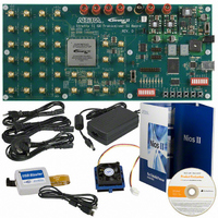
SI KIT W/SII GX EP2SGX90N
Manufacturer
Altera
Series
Stratix® IIr
Type
DSPr
Datasheet
1.DK-SI-2SGX90N.pdf
(38 pages)
Specifications of DK-SI-2SGX90N
Contents
Dev Board, Quartus®II Web Edition, Cables, Accessories, Reference Designs and Demos
For Use With/related Products
Stratix ll GX 2SGX90N
Lead Free Status / RoHS Status
Lead free / RoHS Compliant
Other names
544-1724
Available stocks
Company
Part Number
Manufacturer
Quantity
Price


Measuring
Signal Eye
Diagrams of
Transmitted
Data
Altera Corporation
June 2006
f
■
The on-board EP2SGX90E device’s embedded transceivers support up to
12 transceiver channels. Each transceiver channel has a transmitter and a
receiver. Designers can preset Stratix II GX transceiver functions using
the Quartus II software.
Stratix II GX devices are designed with superior pre-emphasis and
equalization. Pre-emphasis conditions the signal prior to transmission
resulting in an open eye at the far end, while equalization opens the eye
in the receiver. Pre-emphasis and equalization ensure optimal signal
integrity.
In this section, you will walk through the process of measuring signal eye
diagrams of transmitted data.
The following lists the required test equipment:
■
■
■
For information on using Altera megafunctions to customize transceiver
channels, refer to the Stratix II GX alt2gxb Megafunction User Guide
chapter of the Stratix II GX Device Handbook, Volume 2.
Set Up The Testing Environment
This section provides the steps in setting up a testing environment.
Depending on the design running on the development board, one or
more of the six transmitter channels will transmit serial data.
Assuming the design is successfully running on the Stratix II GX
transceiver signal integrity board, the following steps walk you through
the process of measuring eye-diagrams of transmitted data.
●
Freeze Display—When the Freeze Display button is pressed, the
display field is not changed. However the counting is not stopped.
When the Unfreeze Display is pressed, the current running values
are shown.
Sampling oscilloscope with Infinite Persistence display capability,
such as Tektronix TDS8000
Two length matched 50-Ω SMA cables for transmission data out
(TX_Px and TX_Nx) with at least 18GHZ bandwidth.
One 50-ohm SMA cable for the Trigger input to the oscilloscope.
sending a high frequency data pattern, the Data Chk Status box
will also show Unsync’d. This is because the error checker does
not monitor for high frequency error data patterns.
Error status indicates that the error checker is detecting errors in
the received pattern.
Transceiver Signal Integrity Development Kit, Stratix II GX Edition
Getting Started User Guide
Getting Started
2–17
Related parts for DK-SI-2SGX90N
Image
Part Number
Description
Manufacturer
Datasheet
Request
R

Part Number:
Description:
KIT DEV STRATIX IV 4SGX230N/C2
Manufacturer:
Altera
Datasheet:

Part Number:
Description:
KIT DEV STRATIX IV TRANSCEIVER
Manufacturer:
Altera
Datasheet:

Part Number:
Description:
KIT DEV STRATIX V FPGA 5SGXEA7
Manufacturer:
Altera
Datasheet:

Part Number:
Description:
Programmable Logic IC Development Tools FPGA Starter Kit For Stratix V 5SGXEA7
Manufacturer:
Altera Corporation
Part Number:
Description:
Programmable Logic IC Development Tools FPGA Starter Kit For Stratix V 5SGTMC7
Manufacturer:
Altera Corporation
Part Number:
Description:
Programmable Logic IC Development Tools FPGA Starter Kit For Stratix V 5SGTMC7 ES
Manufacturer:
Altera Corporation

Part Number:
Description:
CYCLONE II STARTER KIT EP2C20N
Manufacturer:
Altera
Datasheet:
Part Number:
Description:
CPLD, EP610 Family, ECMOS Process, 300 Gates, 16 Macro Cells, 16 Reg., 16 User I/Os, 5V Supply, 35 Speed Grade, 24DIP
Manufacturer:
Altera Corporation
Datasheet:
Part Number:
Description:
CPLD, EP610 Family, ECMOS Process, 300 Gates, 16 Macro Cells, 16 Reg., 16 User I/Os, 5V Supply, 15 Speed Grade, 24DIP
Manufacturer:
Altera Corporation
Datasheet:
Part Number:
Description:
Manufacturer:
Altera Corporation
Datasheet:
Part Number:
Description:
CPLD, EP610 Family, ECMOS Process, 300 Gates, 16 Macro Cells, 16 Reg., 16 User I/Os, 5V Supply, 30 Speed Grade, 24DIP
Manufacturer:
Altera Corporation
Datasheet:
Part Number:
Description:
High-performance, low-power erasable programmable logic devices with 8 macrocells, 10ns
Manufacturer:
Altera Corporation
Datasheet:
Part Number:
Description:
High-performance, low-power erasable programmable logic devices with 8 macrocells, 7ns
Manufacturer:
Altera Corporation
Datasheet: