DK-PCI-2C35N Altera, DK-PCI-2C35N Datasheet - Page 18
DK-PCI-2C35N
Manufacturer Part Number
DK-PCI-2C35N
Description
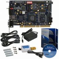
PCI KIT W/CYCLONE II EP2C35N
Manufacturer
Altera
Series
Cyclone® IIr
Type
FPGA: PCI Development Kitr
Datasheet
1.DK-PCI-2C35N.pdf
(40 pages)
Specifications of DK-PCI-2C35N
Contents
Dev Board, Quartus®II Web Edition, Cables, Accessories, Reference Designs and Demos
For Use With/related Products
Cyclone ll 2C35N
Lead Free Status / RoHS Status
Lead free / RoHS Compliant
Other names
544-1733
Available stocks
Company
Part Number
Manufacturer
Quantity
Price


Install the Board in Your PC
Install the Board
in Your PC
Figure 2–3. Cyclone II EP2C35 PCI Development Board
2–8
PCI Development Kit, Cyclone II Edition Getting Started User Guide
User (Down) & Safe (Up)
RS-232 Tx LED(D18)
RS-232 Rx LED (D17)
(D13 through D15)
Power Indicators
RS-232 (J12)
Select Switch (J3)
SMA Clock (J5)
10/100 Ethernet
(D10 Botton Red)
EPCS64 Device
Connector (RJ1)
(D10 Top Green)
JTAG Connector (J8)
Configuration
Configuration
Status LED
Done LED
Button Switches
User Push-
(S1, S5)
PCI Connector (J13)
Power Switch
(D1 through D8)
Cyclone II Device (U9)
You must install the Cyclone II EP2C35 PCI development board (see
Figure
Cyclone II Edition CD-ROM. To install the board in your PC, turn off your
PC and install the board in an available PCI slot.
1
When you power-up the PC, the Cyclone II device is configured with the
default, factory-programmed design stored in flash memory. After the
device is configured, the user LEDs (D1-D8) blink and the CONF DONE
LED (D10) illuminates. This is a power-up indication that the board is
functional and the Cyclone II device has been successfully configured.
User LEDs
(SW1)
Push-Button
Reconfigure
Switch (S2)
2–3) in your PC after you have installed the PCI Development Kit,
Ensure that the EPCS64 device select switch (J3) is in the Up
position (i.e., toward the component side of the board). If the
switch is not in the Up position, your board will not function
properly.
Core Version a.b.c variable
Reset
User
(S3)
Mictor Probe
Connector (J4)
10/100 Ethernet
MAC/PHY (U3)
User DIP Switch
Bank (S4)
(U20 through U24 on back)
PCI Level Converters
(U13 through U17)
Altera Daughter
Card Interface
(J1, J6, J7)
Ground Test Point (TP1)
Safe (Factory-Programmed)
DDR2 SDRAM
VREF Test Point (TP4)
Altera Corporation
Connector (J11)
Power Supply Input
(U6, U10)
EPCS64 Device (U7)
User-Programmable
Active Serial
EPCS64 Device
Interface
(U19 on back)
May 2005
Related parts for DK-PCI-2C35N
Image
Part Number
Description
Manufacturer
Datasheet
Request
R

Part Number:
Description:
Cyclone IV Tranceiver Development Kit
Manufacturer:
Altera
Datasheet:

Part Number:
Description:
Development Software ispLEVER Dev Kit Windows upgrade
Manufacturer:
Lattice

Part Number:
Description:
RELAY MINI PWR 8A 24VDC PC MNT
Manufacturer:
Panasonic Electric Works
Datasheet:
Part Number:
Description:
RELAY MINI PWR 8A 5VDC PC MNT
Manufacturer:
Panasonic Electric Works
Datasheet:
Part Number:
Description:
RELAY MINI PWR 8A 12VDC PC MNT
Manufacturer:
Panasonic Electric Works
Datasheet:

Part Number:
Description:
RELAY MINI PWR 10A 5VDC PC MNT
Manufacturer:
Panasonic Electric Works
Datasheet:
Part Number:
Description:
RELAY MINI PWR 10A 12VDC PC MNT
Manufacturer:
Panasonic Electric Works
Datasheet:
Part Number:
Description:
RELAY MINI PWR 10A 24VDC PC MNT
Manufacturer:
Panasonic Electric Works
Datasheet:

Part Number:
Description:
SOCKET RELAY PC MNT FOR DK1A1B
Manufacturer:
Panasonic Electric Works
Datasheet:

Part Number:
Description:
SOCKET RELAY PC MNT FOR DK1A
Manufacturer:
Panasonic Electric Works
Datasheet:


Part Number:
Description:
CPLD, EP610 Family, ECMOS Process, 300 Gates, 16 Macro Cells, 16 Reg., 16 User I/Os, 5V Supply, 35 Speed Grade, 24DIP
Manufacturer:
Altera Corporation
Datasheet:
Part Number:
Description:
CPLD, EP610 Family, ECMOS Process, 300 Gates, 16 Macro Cells, 16 Reg., 16 User I/Os, 5V Supply, 15 Speed Grade, 24DIP
Manufacturer:
Altera Corporation
Datasheet: