TOOLSTICK542PP Silicon Laboratories Inc, TOOLSTICK542PP Datasheet - Page 273
TOOLSTICK542PP
Manufacturer Part Number
TOOLSTICK542PP
Description
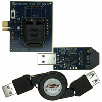
PLATFORM PROG TOOLSTICK F542
Manufacturer
Silicon Laboratories Inc
Series
ToolStickr
Type
Microcontroller Programmerr
Specifications of TOOLSTICK542PP
Contents
2 Boards and USB Connecting Cable
Processor To Be Evaluated
C8051F542
Interface Type
USB
Operating Supply Voltage
2.7 V to 3.6 V
Lead Free Status / RoHS Status
Lead free / RoHS Compliant
For Use With/related Products
C8051F542
Lead Free Status / Rohs Status
Lead free / RoHS Compliant
Other names
336-1718


D
Revision 0.1 to Revision 1.0
Note: All items from the C8051F54x Errata dated November 5th, 2009 are incorporated into this data sheet.
Revision 1.0 to Revision 1.1
OCUMENT
Updated “2. Ordering Information” to include -A (Automotive) devices and automotive qualification
information.
Updated Figure 4.6.
Updated supply current related specifications throughout “6. Electrical Characteristics” .
Updated SFR Definition 7.1 (REF0CN) to change VREF high setting to 2.20 V from 2.25 V.
Updated Figure 8.1 to indicate that Comparators are powered from V
Updated the Gain Table in “5.3.1. Calculating the Gain Value” to fix the ADC0GNH Value in the last row.
Updated Table 10.1 with correct timing for all branch instructions, MOVC, and CPL A.
Updated Table 14.1 to indicate behavior when performing a Flash operation in reserved space.
Updated “14.1. Programming the Flash Memory” to clarify behavior of 8-bit MOVX instructions and
when writing/erasing Flash.
Updated SFR Definition 14.3 (FLSCL) to include FLEWT bit definition. This bit must be set before
writing or erasing Flash. Also updated Table 6.5 to reflect new Flash Write and Erase timing.
Updated “16.7. Flash Error Reset” with an additional cause of a Flash Error reset.
Updated “18.1.3. Interfacing Port I/O in a Multi-Voltage System” to remove note regarding interfacing to
voltages above VIO.
Updated “20. SMBus” to remove all hardware ACK features, including SMB0ADM and SMB0ADR
SFRs.
Updated SFR Definition 21.1(SCON0) to correct SFR Page to 0x00 from All Pages.
Updated CP Register Definition 24.2 with proper Device ID.
Updated “1. System Overview” with a voltage range specification for the internal oscillator.
Updated Figure 5.4, “12-Bit ADC Burst Mode Example With Repeat Count Set to 4,” on page 33 with
new timing diagram when using CNVSTR pin.
Updated Table 6.6, “Internal High-Frequency Oscillator Electrical Characteristics,” on page 53 with new
conditions for the internal oscillator accuracy. The internal oscillator accuracy is dependent on the
operating voltage range.
Updated “6. Electrical Characteristics” to remove the internal oscillator curve across temperature
diagram.
Updated SFR Definition 7.1 (REF0CN) with oscillator suspend requirement for ZTCEN.
Fixed incorrect cross references in “8. Comparators” .
Updated SFR Definition 9.1 (REG0CN) with a new definition for Bit 6. The bit 6 reset value is 1b and
must be written to 1b.
Updated Figure 11.2, “Flash Program Memory Map,” on page 86 with correct address for start of lock
byte page from 0x3900 to 0x3A00.
Updated “15.3. Suspend Mode” with note regarding ZTCEN.
Added Port 2 Event and Port 3 Event to wake-up sources in “17.2.1. Internal Oscillator Suspend Mode”
Updated “19. Local Interconnect Network (LIN)” with a voltage range specification for the internal
oscillator.
Updated LIN Register Definitions for LIN0MUL and LIN0DIV to correct the reset value.
Updated C2 Register Definitions 25.2 and 25.3 with correct C2 and SFR addresses.
C
HANGE
L
IST
Rev. 1.1
IO
and not V
C8051F54x
DDA
.
273
Related parts for TOOLSTICK542PP
Image
Part Number
Description
Manufacturer
Datasheet
Request
R

Part Number:
Description:
KIT TOOL EVAL SYS IN A USB STICK
Manufacturer:
Silicon Laboratories Inc
Datasheet:

Part Number:
Description:
TOOLSTICK DEBUG ADAPTER
Manufacturer:
Silicon Laboratories Inc
Datasheet:

Part Number:
Description:
TOOLSTICK BASE ADAPTER
Manufacturer:
Silicon Laboratories Inc
Datasheet:

Part Number:
Description:
TOOLSTICK DAUGHTER CARD
Manufacturer:
Silicon Laboratories Inc
Datasheet:

Part Number:
Description:
TOOLSTICK DAUGHTER CARD
Manufacturer:
Silicon Laboratories Inc
Datasheet:

Part Number:
Description:
TOOLSTICK DAUGHTER CARD
Manufacturer:
Silicon Laboratories Inc
Datasheet:

Part Number:
Description:
TOOLSTICK DAUGHTER CARD
Manufacturer:
Silicon Laboratories Inc
Datasheet:

Part Number:
Description:
KIT STARTER TOOLSTICK
Manufacturer:
Silicon Laboratories Inc
Datasheet:

Part Number:
Description:
KIT UNIVERSITY TOOLSTICK STARTER
Manufacturer:
Silicon Laboratories Inc
Datasheet:

Part Number:
Description:
DAUGHTER CARD TOOLSTICK F330
Manufacturer:
Silicon Laboratories Inc
Datasheet:

Part Number:
Description:
CARD DAUGHTER UNIVRSTY TOOLSTICK
Manufacturer:
Silicon Laboratories Inc
Datasheet:

Part Number:
Description:
DAUGHTER CARD TOOLSTICK F582
Manufacturer:
Silicon Laboratories Inc
Datasheet:

Part Number:
Description:
DAUGHTER CARD TOOLSTICK F500
Manufacturer:
Silicon Laboratories Inc
Datasheet:

Part Number:
Description:
DAUGHTER CARD TOOLSTICK F540
Manufacturer:
Silicon Laboratories Inc
Datasheet:

Part Number:
Description:
DAUGHTER CARD TOOLSTICK F560
Manufacturer:
Silicon Laboratories Inc
Datasheet: