SF4-DC5V Panasonic Electric Works, SF4-DC5V Datasheet - Page 4
SF4-DC5V
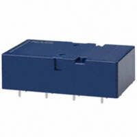
Manufacturer Part Number
SF4-DC5V
Description
RELAY SAFETY PC MNT 8PST 6A 5VDC
Manufacturer
Panasonic Electric Works
Series
SFr
Datasheet
1.SF2-DC12V.pdf
(7 pages)
Specifications of SF4-DC5V
Relay Type
Safety
Contact Form
8PST (4 Form A, 4 Form B)
Contact Rating (current)
6A
Switching Voltage
250VAC
Coil Type
Standard
Coil Current
100mA
Coil Voltage
5VDC
Turn On Voltage (max)
3.75 VDC
Turn Off Voltage (min)
0.75 VDC
Mounting Type
Through Hole
Termination Style
PC Pin
Circuit
8PST (4 Form A, 4 Form B)
Contact Rating @ Voltage
6A @ 250VAC
Control On Voltage (max)
3.75 VDC
Control Off Voltage (min)
0.75 VDC
Lead Free Status / RoHS Status
Lead free / RoHS Compliant
Other names
255-1414
Available stocks
Company
Part Number
Manufacturer
Quantity
Price


SAFETY STRUCTURE OF SF RELAYS
This SF relay design ensures that
subsequent operations shut down and can
automatically return to a safe state when
the SF relay suffers overloading and other
circuit abnormalities (unforeseen
1. Forced operation method
2. Independent operation method
3. Separate chamber method
4. High-efficiency 4-gap balanced
5. 2a2b contact
(2a2b, 3a1b, 4a4b types)
(2a2b, 3a1b, 4a4b types)
armature structure
(2a2b, 3a1b, 4a4b types)
3a1b contact
4a4b contact
(4a4b type)
The two contacts “a” and “b” are coupled with the same
card. The operation of each contact is regulated by the
movement of the other contact.
None of four contacts are held in position by the armature.
Even though one of the external N.O. contacts has
welded, the other three contacts have returned owing to
the de-energizing of the coil.
The use of high-efficiency magnetically polarized circuits
and 4-gap balanced armature structure means that
springs are not required.
Structure with independent COM contact of (2a2b),
(3a1b), (4a4b) contacts.
kept apart by a body/card separator or by the card itself.
In independent chambers, the contacts "a" and "b" are
Return
Return
externally caused circuit or device
breakdowns, end of life incidents, and
noise, surge, and environmental
influences) owing to contact welding,
spring fusion or, in the worst-case
Card
Case separator
Structure
1
Weld
Card
Min. 0.5 mm
Contact a
Contact b
2
External NO
contact weld
Return
Contact a
Body
separator
Contact b
.020 inch
scenario, relay breakdown (coil rupture,
faulty operation, faulty return, and fatigue
and breakage of the operating spring and
return spring), and even in the event of
end of life.
Even when one contact is welded closed,
the other maintains a gap of greater than
0.5 mm
In the diagram on the left, the lower
contact "b" have welded but the upper con-
tact "a" maintain at a gap of greater than
0.5 mm
Subsequent contact movement is
suspended and the weld can be detected
Enables design of safety circuits that allow
weld detection and return at an early stage.
As shown at the top right of the diagram on
the left, if the external N.O. contact welds, a
0.5 mm
Each of the other contacts returns to N.O.
because the coil is no longer energized.
Prevents shorting and fusing of springs and
spring failure owing to short-circuit current.
As shown on the diagram on the left, even
if the operating springs numbered 1 and 2
there is no shorting between "a" and "b"
contacts.
Does away with return faults due to fatigue
or breakage of the return spring, especially
stoppage during contact states.
Independent COM enables differing pole
circuit configurations. This makes it
possible to design various kinds of control
circuits and safety circuits.
.020
.020
.020 inch
inch.
inch.
Operation
gap is maintained.
SF
261
Related parts for SF4-DC5V
Image
Part Number
Description
Manufacturer
Datasheet
Request
R

Part Number:
Description:
RELAY SAFETY PC MNT 8PST 6A 24V
Manufacturer:
Panasonic Electric Works
Datasheet:

Part Number:
Description:
Manufacturer:
Panasonic Electric Works
Datasheet:
Part Number:
Description:
Manufacturer:
Panasonic Electric Works
Datasheet:

Part Number:
Description:
CONN SOCKET P4 .4MM 50POS SMD
Manufacturer:
Panasonic Electric Works
Datasheet:
Part Number:
Description:
CONN SOCKET .8MM 16POS SMD
Manufacturer:
Panasonic Electric Works
Datasheet:
Part Number:
Description:
CONN HEADER .8MM 16POS SMD
Manufacturer:
Panasonic Electric Works
Datasheet:
Part Number:
Description:
CONN SOCKET .8MM 20POS SMD
Manufacturer:
Panasonic Electric Works
Datasheet:
Part Number:
Description:
CONN SOCKET .8MM 20POS SMD
Manufacturer:
Panasonic Electric Works
Datasheet:
Part Number:
Description:
CONN HEADER .8MM 20POS SMD
Manufacturer:
Panasonic Electric Works
Datasheet:
Part Number:
Description:
CONN SOCKET .8MM 22POS SMD
Manufacturer:
Panasonic Electric Works
Datasheet:
Part Number:
Description:
CONN SOCKET .8MM 30POS SMD
Manufacturer:
Panasonic Electric Works
Datasheet:
Part Number:
Description:
CONN HEADER .8MM 30POS SMD
Manufacturer:
Panasonic Electric Works
Datasheet:
Part Number:
Description:
CONN SOCKET .8MM 30POS SMD
Manufacturer:
Panasonic Electric Works
Datasheet:
Part Number:
Description:
CONN SOCKET .8MM 30POS SMD
Manufacturer:
Panasonic Electric Works
Datasheet:
Part Number:
Description:
CONN HEADER .8MM 30POS SMD
Manufacturer:
Panasonic Electric Works
Datasheet: