SF4-DC5V Panasonic Electric Works, SF4-DC5V Datasheet - Page 5
SF4-DC5V
Manufacturer Part Number
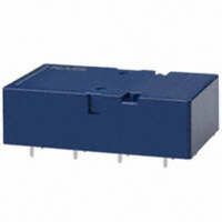
SF4-DC5V
Description
RELAY SAFETY PC MNT 8PST 6A 5VDC
Manufacturer
Panasonic Electric Works
Series
SFr
Datasheet
1.SF2-DC12V.pdf
(7 pages)
Specifications of SF4-DC5V
Relay Type
Safety
Contact Form
8PST (4 Form A, 4 Form B)
Contact Rating (current)
6A
Switching Voltage
250VAC
Coil Type
Standard
Coil Current
100mA
Coil Voltage
5VDC
Turn On Voltage (max)
3.75 VDC
Turn Off Voltage (min)
0.75 VDC
Mounting Type
Through Hole
Termination Style
PC Pin
Circuit
8PST (4 Form A, 4 Form B)
Contact Rating @ Voltage
6A @ 250VAC
Control On Voltage (max)
3.75 VDC
Control Off Voltage (min)
0.75 VDC
Lead Free Status / RoHS Status
Lead free / RoHS Compliant
Other names
255-1414
Available stocks
Company
Part Number
Manufacturer
Quantity
Price


THE OPERATION OF SF RELAYS (when contacts are welded)
SF relays work to maintain a normal operating state even when overloading or short-circuit currents occur. It is also easy to include
weld detection circuits and safety circuits in the design to ensure safety even if contacts weld.
SF
1) 2a2b Type
If the form “b” contacts (Nos. 1 and 3) weld, the armature becomes non-operational and the contact gap of the two form “a” contacts
is maintained at greater than 0.5 mm
If the two form “a” contacts (Nos. 2 and 4) weld, the armature becomes non-operational and the gap between the two form "b"
contacts is maintained at greater than 0.5 mm
The table below shows the state of the other contacts when the current through the welded form “a” contact is 0 V and the rated
voltage is applied through the form “b” contact.
262
No.4
No.3
No.4
No.3
No.4
No.3
Terminal No.
Contact No.
Contact Operation Table
Form “b” Contact Weld
Form “a” Contact Weld
Non-energized
11–12
No.1
Energized
No.2
7–8
No.3
5–6
No.4
9–10
No.1
No.2
No.1
No.2
No.1
No.2
.020
inch. Reliable isolation is thus ensured.
.020
Note: Contact gaps are shown at the initial state.
If the contacts change state owing to loading/breaking
it is necessary to check the actual loading.
Contact No.
No.4
No.3
terminal
No.4
No.3
Non-energized (when no. 2 contact is welded)
Welded
Energized (when no. 1 contact is welded)
No.
inch. Reliable isolation is thus ensured.
Contact No.
1
2
3
4
>0.5
>0.5
State of other contacts
1
>0.5
>0.5
2
>0.5
>0.5
3
No.1
No.2
No.1
No.2
>0.5
>0.5
4
If the No. 1 contact welds.
A gap of greater than 0.5 mm
tained at each of the two form "a" contacts (Nos.
2 and 4).
If the No. 2 contact welds.
Each of the two form "b" contacts (Nos. 1 and 3)
maintains a gap of greater than 0.5 mm
Empty cells: either closed or open
>0.5: contact gap is kept at min. 0.5 mm
.020 inch
is main-
.020
.020 inch
inch.
Related parts for SF4-DC5V
Image
Part Number
Description
Manufacturer
Datasheet
Request
R

Part Number:
Description:
RELAY SAFETY PC MNT 8PST 6A 24V
Manufacturer:
Panasonic Electric Works
Datasheet:

Part Number:
Description:
Manufacturer:
Panasonic Electric Works
Datasheet:
Part Number:
Description:
Manufacturer:
Panasonic Electric Works
Datasheet:

Part Number:
Description:
CONN SOCKET P4 .4MM 50POS SMD
Manufacturer:
Panasonic Electric Works
Datasheet:
Part Number:
Description:
CONN SOCKET .8MM 16POS SMD
Manufacturer:
Panasonic Electric Works
Datasheet:
Part Number:
Description:
CONN HEADER .8MM 16POS SMD
Manufacturer:
Panasonic Electric Works
Datasheet:
Part Number:
Description:
CONN SOCKET .8MM 20POS SMD
Manufacturer:
Panasonic Electric Works
Datasheet:
Part Number:
Description:
CONN SOCKET .8MM 20POS SMD
Manufacturer:
Panasonic Electric Works
Datasheet:
Part Number:
Description:
CONN HEADER .8MM 20POS SMD
Manufacturer:
Panasonic Electric Works
Datasheet:
Part Number:
Description:
CONN SOCKET .8MM 22POS SMD
Manufacturer:
Panasonic Electric Works
Datasheet:
Part Number:
Description:
CONN SOCKET .8MM 30POS SMD
Manufacturer:
Panasonic Electric Works
Datasheet:
Part Number:
Description:
CONN HEADER .8MM 30POS SMD
Manufacturer:
Panasonic Electric Works
Datasheet:
Part Number:
Description:
CONN SOCKET .8MM 30POS SMD
Manufacturer:
Panasonic Electric Works
Datasheet:
Part Number:
Description:
CONN SOCKET .8MM 30POS SMD
Manufacturer:
Panasonic Electric Works
Datasheet:
Part Number:
Description:
CONN HEADER .8MM 30POS SMD
Manufacturer:
Panasonic Electric Works
Datasheet: