58545-1 Tyco Electronics, 58545-1 Datasheet - Page 2
58545-1
Manufacturer Part Number
58545-1
Description
DIE SET UNINSULATED TERMINALS
Manufacturer
Tyco Electronics
Series
Pro-Crimper™ III, Solistrand™r
Specifications of 58545-1
Connector Type
Terminals and Splices
Crimp Handle
A9996-ND
Crimp Or Cable Size
10-22 AWG
Wire Size (awg)
22-10
For Use With
SOLISTRAND Uninsulated Terminals And Splices
Lead Free Status / RoHS Status
Not applicable / Not applicable
Other names
A9813


3. DIE ASSEMBLY INSTALLATION AND REMOVAL
2 of 5
1. Open the tool handles and remove the two die
retaining screws from the tool jaws.
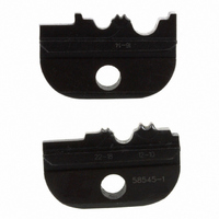
2. Place the upper die in the stationary jaw of the
tool frame so that the largest indenter is facing
inward. See Figure 2.
3. Insert the die retaining screw through the
stationary jaw and through the die. Tighten the
screw just enough to hold the die in place. Do not
tighten the screw completely at this time.
4. Place the lower die in the moving jaw of the tool
frame so that the largest anvil is facing inward. See
Figure 2.
5. Insert the die retaining screw through the
moving jaw and through the die. Tighten the screw
just enough to hold the die in place. Do not tighten
the screw completely at this time.
6. Carefully close the tool handles, making sure
that the anvils and indenters align properly.
Continue closing the tool handles until the ratchet
has engaged sufficiently to hold the dies in place,
then tighten both die retaining screws.
7. To disassemble, open the tool handles until the
ratchet releases, remove the two die retaining
screws, and slide the dies out of the tool jaws.
Indenters
Upper Die
Stationary Jaw
Lower Die
PRO–CRIMPER II Hand Tool Assembly 58546–1
Anvils
Figure 2
4. CRIMPING PROCEDURE
Refer to Figure 1 and select wire of the specified size
and insulation diameter. Strip the wire to the length
indicated, taking care not to nick or cut wire strands.
Select an applicable splice and identify the
appropriate crimping chamber according to the wire
size markings on the dies. Refer to Figure 3 and
proceed as follows:
NOTE
1. Hold tool so that the back (wire side) is facing
you. Squeeze tool handles together until the
ratchet releases, then allow them to open fully.
2. Center the splice wire barrel on the anvil of the
upper die as shown in Figure 3. If visible, be sure
to place the brazed seam on the splice toward the
indenter.
3. Hold the wire barrel in place and squeeze the
tool handles together until ratchet engages
sufficiently to hold the splice in position. Do NOT
deform the insulation barrel or wire barrel.
4. Insert stripped wire into the wire barrel, making
sure that the insulation does not enter the wire
barrel. See Figure 3.
5. Holding wire in place, squeeze tool handles
together until ratchet releases. Allow tool handles
to open, then remove crimped splice.
Before using the tool, the crimping chambers and
tool ratchet should be inspected as specified in
Section 5, CRIMP HEIGHT INSPECTION, and
Section 6, SHUT HEIGHT ADJUSTMENT.
Die Retaining
Screws
408–4047
Rev D