58545-1 Tyco Electronics, 58545-1 Datasheet - Page 4
58545-1
Manufacturer Part Number
58545-1
Description
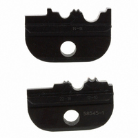
DIE SET UNINSULATED TERMINALS
Manufacturer
Tyco Electronics
Series
Pro-Crimper™ III, Solistrand™r
Specifications of 58545-1
Connector Type
Terminals and Splices
Crimp Handle
A9996-ND
Crimp Or Cable Size
10-22 AWG
Wire Size (awg)
22-10
For Use With
SOLISTRAND Uninsulated Terminals And Splices
Lead Free Status / RoHS Status
Not applicable / Not applicable
Other names
A9813


5. CRIMP HEIGHT INSPECTION
This inspection requires the use of plug gages
conforming to the dimensions provided in Figure 5.
Tyco Electronics does not manufacture or market
these gages. To gage the crimping chamber, proceed
as follows:
“R”
4 of 5
(Die Marking)
Configuration
CHAMBER
CRIMPING
Die Closure
1. Remove traces of oil or dirt from the crimping
chamber and plug gage.
2. Close the tool handles until the dies have
bottomed. Do NOT force dies beyond initial
contact.
3. Align the GO element with the crimping
chamber. Push element straight into the crimping
chamber without using force.
Dim.
GO
22–18
16–14
12–10
NO–GO Element May Start Entry, But Must Not
Pass Completely Through Crimping Chamber
GO Element Must Pass Completely
Through Crimping Chamber
12.7 [.50]
Min Typ
Suggested Plug Gage Design
[.0450–.0453]
[.0530–.0533]
[.0750–.0753]
1.143–1.151
1.346–1.354
1.905–1.913
GO
GAGE ELEMENT DIMENSIONS
Figure 5
50.8 [2.00]
Min Typ
[.0529–.0530]
[.0609–.0610]
[.0829–.0830]
1.344–1.346
1.547–1.549
2.106–2.108
NO–GO
PRO–CRIMPER II Hand Tool Assembly 58546–1
1.57 [.062]
1.98 [.078]
2.77 [.109]
(Radius)
“R”
NO–GO
Dim.
“R”
If the crimping chamber conforms to the gage
inspection, the tool is considered dimensionally
correct, and should be lubricated with a THIN coat of
any good SAE 20 motor oil. If not, the tool must be
returned to Tyco Electronics for further evaluation and
repair. Refer to Section 8, REPLACEMENT.
For additional information regarding the use of a plug
gage, refer to instruction sheet 408–7424.
6. SHUT HEIGHT ADJUSTMENT
The frame assembly ratchet mechanism features an
adjustment wheel with numbered settings. If the dies
do not bottom, adjust the ratchet as follows:
The GO element must pass completely through the
crimping chamber. See Figure 5.
4. Align the NO–GO element and try to insert it
straight into the same crimping chamber. The
NO–GO element may start entry, but must not
pass completely through the crimping chamber.
See Figure 5.
1. Remove the lockscrew from the ratchet
adjustment wheel.
2. With a screwdriver, adjust the ratchet wheel
from the opposite side of the frame.
3. Observe the ratchet adjustment wheel. If the
dies do not bottom, rotate the adjustment wheel
COUNTERCLOCKWISE to a higher–numbered
setting.
4. Replace the lockscrew.
Ratchet
Adjustment
Wheel
Screwdriver
Lockscrew
Figure 6
(Figure 6)
408–4047
Rev D