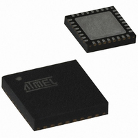
ATTINY461-20MU Atmel, ATTINY461-20MU Datasheet - Page 79

ATTINY461-20MU
Manufacturer Part Number
ATTINY461-20MU
Description
IC AVR MCU 4K 20MHZ 32-QFN
Manufacturer
Atmel
Series
AVR® ATtinyr
Specifications of ATTINY461-20MU
Core Processor
AVR
Core Size
8-Bit
Speed
20MHz
Connectivity
USI
Peripherals
Brown-out Detect/Reset, POR, PWM, WDT
Number Of I /o
16
Program Memory Size
4KB (2K x 16)
Program Memory Type
FLASH
Eeprom Size
256 x 8
Ram Size
256 x 8
Voltage - Supply (vcc/vdd)
2.7 V ~ 5.5 V
Data Converters
A/D 11x10b
Oscillator Type
Internal
Operating Temperature
-40°C ~ 85°C
Package / Case
32-VQFN Exposed Pad, 32-HVQFN, 32-SQFN, 32-DHVQFN
Processor Series
ATTINY4x
Core
AVR8
Data Bus Width
8 bit
Data Ram Size
256 B
Interface Type
2-Wire, SPI, USI
Maximum Clock Frequency
20 MHz
Number Of Programmable I/os
16
Number Of Timers
2
Maximum Operating Temperature
+ 85 C
Mounting Style
SMD/SMT
3rd Party Development Tools
EWAVR, EWAVR-BL
Development Tools By Supplier
ATAVRDRAGON, ATSTK500, ATSTK600, ATAVRISP2, ATAVRONEKIT
Minimum Operating Temperature
- 40 C
On-chip Adc
10 bit, 11 Channel
For Use With
ATSTK600-DIP40 - STK600 SOCKET/ADAPTER 40-PDIPATAVRBC100 - REF DESIGN KIT BATTERY CHARGER770-1007 - ISP 4PORT ATMEL AVR MCU SPI/JTAG
Lead Free Status / RoHS Status
Lead free / RoHS Compliant
Available stocks
Company
Part Number
Manufacturer
Quantity
Price
Company:
Part Number:
ATTINY461-20MU
Manufacturer:
KODENSHI
Quantity:
991
Company:
Part Number:
ATTINY461-20MUR
Manufacturer:
ATMEL
Quantity:
5 560
- Current page: 79 of 242
- Download datasheet (5Mb)
11.7.4
11.7.5
11.8
2588E–AVR–08/10
Timer/Counter Timing Diagrams
8-bit Input Capture Mode
16-bit Input Capture Mode
cases to consider in the Normal mode, a new counter value can be written anytime. The Output
Compare Unit can be used to generate interrupts at some given time.
The Timer/Counter0 can also be used in an 8-bit Input Capture mode, see
77
The Timer/Counter0 can also be used in a 16-bit Input Capture mode, see
77
The Timer/Counter is a synchronous design and the timer clock (clk
clock enable signal in the following figures. The figures include information on when Interrupt
Flags are set.
shows the count sequence close to the MAX value.
Figure 11-7. Timer/Counter Timing Diagram, no Prescaling
Figure 11-8
Figure 11-8. Timer/Counter Timing Diagram, with Prescaler (f
Figure 11-9 on page 80
TCNTn
(clk
TCNTn
(clk
TOVn
TOVn
clk
clk
clk
clk
for bit settings. For full description, see the section
for bit settings. For full description, see the section
I/O
I/O
I/O
Tn
I/O
Tn
/1)
/8)
shows the same timing data, but with the prescaler enabled.
Figure 11-7
MAX - 1
MAX - 1
shows the setting of OCF0A and OCF0B in Normal mode.
contains timing data for basic Timer/Counter operation. The figure
MAX
MAX
“Input Capture Unit” on page
“Input Capture Unit” on page
clk_I/O
BOTTOM
BOTTOM
/8)
T0
) is therefore shown as a
Table 11-3 on page
Table 11-3 on page
BOTTOM + 1
BOTTOM + 1
75.
75.
79
Related parts for ATTINY461-20MU
Image
Part Number
Description
Manufacturer
Datasheet
Request
R

Part Number:
Description:
Manufacturer:
Atmel Corporation
Datasheet:

Part Number:
Description:
Manufacturer:
Atmel Corporation
Datasheet:

Part Number:
Description:
IC MCU AVR 4K FLASH 20MHZ 20SOIC
Manufacturer:
Atmel
Datasheet:

Part Number:
Description:
MCU AVR 4K FLASH 15MHZ 32-QFN
Manufacturer:
Atmel
Datasheet:

Part Number:
Description:
MCU AVR 4KB FLASH 15MHZ 32-VQFN
Manufacturer:
Atmel
Datasheet:

Part Number:
Description:
MCU AVR 4KB FLASH 20MHZ 20SOIC
Manufacturer:
Atmel
Datasheet:

Part Number:
Description:
IC MCU AVR 4K 20MHZ 32QFN
Manufacturer:
Atmel
Datasheet:

Part Number:
Description:
Microcontrollers (MCU) 4kB Flash 0.256kB EEPROM 16 I/O Pins
Manufacturer:
Atmel
Datasheet:

Part Number:
Description:
IC, MCU, 8BIT, 2K FLASH, 20SOIC
Manufacturer:
Atmel
Datasheet:

Part Number:
Description:
IC, MCU, 8BIT, 2K FLASH, 20PDIP
Manufacturer:
Atmel
Datasheet:


