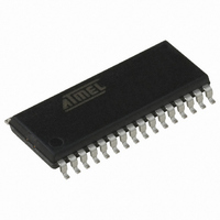
AT90PWM3B-16SU Atmel, AT90PWM3B-16SU Datasheet - Page 314

AT90PWM3B-16SU
Manufacturer Part Number
AT90PWM3B-16SU
Description
IC MCU AVR RISC 8K FLASH 32-SOIC
Manufacturer
Atmel
Series
AVR® 90PWM Lightingr
Specifications of AT90PWM3B-16SU
Core Processor
AVR
Core Size
8-Bit
Speed
16MHz
Connectivity
SPI, UART/USART
Peripherals
Brown-out Detect/Reset, POR, PWM, WDT
Number Of I /o
27
Program Memory Size
8KB (8K x 8)
Program Memory Type
FLASH
Eeprom Size
512 x 8
Ram Size
512 x 8
Voltage - Supply (vcc/vdd)
2.7 V ~ 5.5 V
Data Converters
A/D 11x10b; D/A 1x10b
Oscillator Type
Internal
Operating Temperature
-40°C ~ 105°C
Package / Case
32-SOIC (7.5mm Width)
Processor Series
AT90PWMx
Core
AVR8
Data Bus Width
8 bit
Data Ram Size
512 B
Interface Type
SPI/USART
Maximum Clock Frequency
16 MHz
Number Of Programmable I/os
27
Number Of Timers
2
Operating Supply Voltage
2.7 V to 5.5 V
Maximum Operating Temperature
+ 105 C
Mounting Style
SMD/SMT
3rd Party Development Tools
EWAVR, EWAVR-BL
Development Tools By Supplier
ATAVRDRAGON, ATSTK500, ATSTK600, ATAVRISP2, ATAVRONEKIT, ATAVRFBKIT, ATAVRISP2
Minimum Operating Temperature
- 40 C
On-chip Adc
11-ch x 10-bit
On-chip Dac
1-chx10-bit
Controller Family/series
AVR PWM
Eeprom Memory Size
512Byte
Ram Memory Size
512Byte
Cpu Speed
16MHz
Rohs Compliant
Yes
For Use With
ATSTK600-SOIC - STK600 SOCKET/ADAPTER FOR SOIC770-1007 - ISP 4PORT ATMEL AVR MCU SPI/JTAGATAVRMC200 - KIT EVAL FOR AT90PWM3 ASYNCATAVRFBKIT - KIT DEMO BALLAST FOR AT90PWM2ATAVRISP2 - PROGRAMMER AVR IN SYSTEMATSTK520 - ADAPTER KIT FOR 90PWM
Lead Free Status / RoHS Status
Lead free / RoHS Compliant
Available stocks
Company
Part Number
Manufacturer
Quantity
Price
Company:
Part Number:
AT90PWM3B-16SU
Manufacturer:
Atmel
Quantity:
4 000
Part Number:
AT90PWM3B-16SU
Manufacturer:
MICROCHIP/微芯
Quantity:
20 000
- Current page: 314 of 361
- Download datasheet (7Mb)
27.2.1.1
27.2.1.2
314
AT90PWM2/3/2B/3B
Example 1
Example 2
are controlled by the Power Reduction Register. See
details.
Table 27-1.
Table 27-2.
It is possible to calculate the typical current consumption based on the numbers from
for other V
Calculate the expected current consumption in idle mode with USART, TIMER1, and SPI
enabled at V
add 18% for the USART, 26% for the SPI, and 11% for the TIMER1 module. Reading from
ure 27-5
total current consumption in idle mode with USART0, TIMER1, and SPI enabled, gives:
Same conditions as in example 1, but in active mode instead. From
we see that we need to add 3.3% for the USART, 4.8% for the SPI, and 2.0% for the TIMER1
module. Reading from
PRR bit
PRPSC2
PRPSC1
PRPSC0
PRTIM1
PRTIM0
PRSPI
PRUSART
PRADC
PRR bit
PRPSC2
PRPSC1
PRPSC0
PRTIM1
PRTIM0
PRSPI
PRUSART
PRADC
I
CC
total
≈
, we find that the idle current consumption is ~0,17mA at V
0.17mA
CC
CC
and frequency settings than listed in
Additional Current Consumption for the different I/O modules (absolute values)
Additional Current Consumption (percentage) in Active and Idle mode
= 3.0V and F = 1MHz. From
•
(
1
Additional Current consumption
compared to Active with external
clock
(see
10%
10%
10%
8.5%
4.3%
5.3%
15.6
10.5%
+
Typical numbers
350 uA
350 uA
350 uA
300 uA
200 uA
250 uA
550 uA
350 uA
0.36
Figure 27-1
Figure 27-1
+
0.22
V
CC
+
= 3V, F = 8MHz
, we find that the active current consumption is ~0,6mA at V
0.14
and
)
Figure
≈
0.29mA
Table
27-2)
Table
27-2, third column, we see that we need to
“Power Reduction Register” on page 42
27-1.
Additional Current consumption
compared to Idle with external clock
(see
25%
25%
25%
22%
11%
14%
36
25%
1.3 mA
1.3 mA
1.3 mA
1.15 mA
0.75 mA
0.9 mA
2 mA
1.3 mA
Figure 27-5
CC
V
Table
CC
= 3.0V and F = 1MHz. The
= 5V, F = 16MHz
and
27-2, second column
Figure
4317J–AVR–08/10
Table 27-2
27-6)
Fig-
for
CC
Related parts for AT90PWM3B-16SU
Image
Part Number
Description
Manufacturer
Datasheet
Request
R

Part Number:
Description:
Manufacturer:
Atmel Corporation
Datasheet:

Part Number:
Description:
IC MCU AVR RISC 8K FLASH 32-QFN
Manufacturer:
Atmel
Datasheet:

Part Number:
Description:
MCU AVR 8K FLASH 16MHA 32SOIC
Manufacturer:
Atmel
Datasheet:

Part Number:
Description:
IC AVR MCU FLASH 8K 32QFN
Manufacturer:
Atmel
Datasheet:

Part Number:
Description:
IC AVR MCU FLASH 8K 32SOIC
Manufacturer:
Atmel
Datasheet:

Part Number:
Description:
MCU AVR 8K FLASH 16MHZ 32-QFN
Manufacturer:
Atmel
Datasheet:

Part Number:
Description:
DEV KIT FOR AVR/AVR32
Manufacturer:
Atmel
Datasheet:

Part Number:
Description:
INTERVAL AND WIPE/WASH WIPER CONTROL IC WITH DELAY
Manufacturer:
ATMEL Corporation
Datasheet:

Part Number:
Description:
Low-Voltage Voice-Switched IC for Hands-Free Operation
Manufacturer:
ATMEL Corporation
Datasheet:

Part Number:
Description:
MONOLITHIC INTEGRATED FEATUREPHONE CIRCUIT
Manufacturer:
ATMEL Corporation
Datasheet:

Part Number:
Description:
AM-FM Receiver IC U4255BM-M
Manufacturer:
ATMEL Corporation
Datasheet:

Part Number:
Description:
Monolithic Integrated Feature Phone Circuit
Manufacturer:
ATMEL Corporation
Datasheet:

Part Number:
Description:
Multistandard Video-IF and Quasi Parallel Sound Processing
Manufacturer:
ATMEL Corporation
Datasheet:


