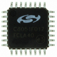
C8051F017-GQ Silicon Laboratories Inc, C8051F017-GQ Datasheet - Page 89

C8051F017-GQ
Manufacturer Part Number
C8051F017-GQ
Description
IC 8051 MCU 32K FLASH 32LQFP
Manufacturer
Silicon Laboratories Inc
Series
C8051F01xr
Specifications of C8051F017-GQ
Program Memory Type
FLASH
Program Memory Size
32KB (32K x 8)
Package / Case
32-LQFP
Core Processor
8051
Core Size
8-Bit
Speed
25MHz
Connectivity
SMBus (2-Wire/I²C), SPI, UART/USART
Peripherals
Brown-out Detect/Reset, POR, PWM, Temp Sensor, WDT
Number Of I /o
8
Ram Size
2.25K x 8
Voltage - Supply (vcc/vdd)
2.7 V ~ 3.6 V
Data Converters
A/D 4x10b; D/A 2x12b
Oscillator Type
Internal
Operating Temperature
-40°C ~ 85°C
Processor Series
C8051F0x
Core
8051
Data Bus Width
8 bit
Data Ram Size
2.25 KB
Interface Type
I2C/SMBus/SPI/UART
Maximum Clock Frequency
25 MHz
Number Of Programmable I/os
8
Number Of Timers
4
Operating Supply Voltage
2.7 V to 3.6 V
Maximum Operating Temperature
+ 85 C
Mounting Style
SMD/SMT
3rd Party Development Tools
PK51, CA51, A51, ULINK2
Development Tools By Supplier
C8051F005DK
Minimum Operating Temperature
- 40 C
On-chip Adc
4-ch x 10-bit
On-chip Dac
2-ch x 12-bit
No. Of I/o's
8
Ram Memory Size
256Byte
Cpu Speed
25MHz
No. Of Timers
4
No. Of Pwm Channels
5
Rohs Compliant
Yes
Lead Free Status / RoHS Status
Lead free / RoHS Compliant
Eeprom Size
-
Lead Free Status / Rohs Status
Lead free / RoHS Compliant
Other names
336-1196
Available stocks
Company
Part Number
Manufacturer
Quantity
Price
Company:
Part Number:
C8051F017-GQ
Manufacturer:
Silicon Labs
Quantity:
135
Company:
Part Number:
C8051F017-GQ
Manufacturer:
Silicon Laboratories Inc
Quantity:
10 000
Company:
Part Number:
C8051F017-GQR
Manufacturer:
Silicon Laboratories Inc
Quantity:
10 000
The lock bits can always be read and cleared to logic 0 regardless of the security setting applied to the block
containing the security bytes. This allows additional blocks to be protected after the block containing the security
bytes has been locked. However, the only means of removing a lock once set is to erase the entire program memory
space by performing a JTAG erase operation (i.e. cannot be done in user firmware). NOTE: Addressing either
security byte while performing a JTAG erase operation will automatically initiate erasure of the entire
program memory space (except for the reserved area). This erasure can only be performed via JTAG. If a
non-security byte in the 0x7C00-0x7DFF page is addressed during erasure, only that page (including the
security bytes) will be erased.
The Flash Access Limit security feature (see Figure 11.3) protects proprietary program code and data from being
read by software running on the C8051F005/06/07/15/16/17 MCUs. This feature provides support for OEMs that
wish to program the MCU with proprietary value-added firmware before distribution. The value-added firmware
can be protected while allowing additional code to be programmed in remaining program memory space later.
The Software Read Limit (SRL) is a 16-bit address that establishes two logical partitions in the program memory
space. The first is an upper partition consisting of all the program memory locations at or above the SRL address,
and the second is a lower partition consisting of all the program memory locations starting at 0x0000 up to (but
excluding) the SRL address. Software in the upper partition can execute code in the lower partition, but is
89
C8051F000/1/2/5/6/7
C8051F010/1/2/5/6/7
FLASH Read Lock Byte
Bits7-0: Each bit locks a corresponding block of memory. (Bit 7 is MSB.)
FLASH Write/Erase Lock Byte
FLASH Access Limit Register (FLACL)
Bits7-0: Each bit locks a corresponding block of memory.
0: Read operations are locked (disabled) for corresponding block across the JTAG interface.
1: Read operations are unlocked (enabled) for corresponding block across the JTAG interface.
0: Write/Erase operations are locked (disabled) for corresponding block across the JTAG interface.
1: Write/Erase operations are unlocked (enabled) for corresponding block across the JTAG interface.
The content of this register is used as the high byte of the 16-bit software read limit address. The 16-
bit read limit address value is calculated as 0xNN00 where NN is replaced by the contents of this
register. Software running at or above this address is prohibited from using the MOVX or MOVC
instructions to read, write, or erase, locations below this address. Any attempts to read locations
below this limit will return the value 0x00.
Program Memory
Figure 11.2. Flash Program Memory Security Bytes
Space
Write/Erase Lock Byte
(This Block locked only if all
other blocks are locked)
Software Read Limit
Read Lock Byte
Reserved
Rev. 1.7
0x807F
0x8000
0x7FFF
0x7E00
0x7DFF
0x7DF
E
0x7DFD
0x0000
Read and Write/Erase Security Bits.
(Bit 7 is MSB.)
Bit
7
6
5
4
3
2
1
0
0x7000 - 0x7DFD
Memory Block
0x6000 - 0x6FFF
0x5000 - 0x5FFF
0x4000 - 0x4FFF
0x3000 - 0x3FFF
0x2000 - 0x2FFF
0x1000 - 0x1FFF
0x0000 - 0x0FFF


