MCP2030DM-TPR Microchip Technology, MCP2030DM-TPR Datasheet - Page 11
MCP2030DM-TPR
Manufacturer Part Number
MCP2030DM-TPR
Description
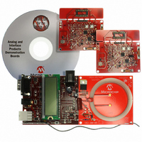
BOARD DEMO PICTAIL MCP2030
Manufacturer
Microchip Technology
Type
Front Endr
Specifications of MCP2030DM-TPR
Frequency
125kHz
For Use With/related Products
MCP2030
Lead Free Status / RoHS Status
Not applicable / Not applicable
Lead Free Status / RoHS Status
Lead free / RoHS Compliant, Not applicable / Not applicable


2.1
© 2006 Microchip Technology Inc.
OVERVIEW
This section describes how to use the MCP2030 Bidirectional Communication Demo
Kit.
The MCP2030 Bidirectional Communication Demo Kit consists of two Transponders
and a Base Station unit. The Transponder consists of an MCP2030 (stand-alone
three-axis analog front-end device), a PIC16F636, and an MCP3421(18-bit
delta-sigma analog-to-digital converter). Unlike the existing PKE Reference Design
System (P/N: APGRD001) from Microchip Technology Inc., this Transponder uses
stand-alone devices for the bidirectional passive keyless entry (PKE) operation. This
system also demonstrates the received signal strength indicator (RSSI) function using
the MCP3421 delta-sigma ADC. When the Transponder receives a Base Station com-
mand, it transmits its ID and sampled RSSI value. By monitoring or mapping the RSSI
values, the user can estimate location or motion of the transponder with respect to the
Base Station unit. For example, for the automotive passive keyless entry (PKE) appli-
cations, the Base Station mounted inside the vehicle can determine whether the tran-
sponder is located inside or outside of the vehicle, or in the front or back seat in the
vehicle.
The Base Station unit consists of a PIC18F4680, a low frequency (LF) power amplifier,
an LF receiver section, a 434 MHz UHF receiver module, an LCD display, and
CAN/LIN transceiver sections. The components in the LF receiver section and the
CAN/LIN transceiver sections are populated on the PCB for future use, but their
functions are not utilized for this demo version. Any user who needs these features can
contact Microchip Technology Inc. for further information.
The MCP2030 Bidirectional Communication Demo Kit has been designed for easy
modification by customers. The firmware of both the Transponder and Base Station
units can be easily modified using the MPLAB
FIGURE 2-1:
Base Station
Chapter 2. System Overview
LCD
434 MHz AM
Transmitter/
Receiver
Receiver
LED
LF
MCP2030 Bidirectional Communication System Block Diagram.
125 kHz
Resonant Circuit
LC Series
COMMUNICATION DEMO KIT
MCP2030 BIDIRECTIONAL
LF Command
(125 kHz)
®
Response
in-circuit serial programmers.
(UHF)
Ant. X
Ant. Y
Ant. Z
125 kHz
LC Parallel
Resonant Circuit
USER’S GUIDE
Transmitter
434 MHz
Transponder
DS51637A-page 7
(PIC16F636)
(MCP3421)
LED
MCU
ADC
Button
SW
Related parts for MCP2030DM-TPR
Image
Part Number
Description
Manufacturer
Datasheet
Request
R

Part Number:
Description:
IC KEYLESS ENTRY AFE 14TSSOP
Manufacturer:
Microchip Technology
Datasheet:

Part Number:
Description:
IC KEYLESS ENTRY AFE 14SOIC
Manufacturer:
Microchip Technology
Datasheet:

Part Number:
Description:
IC KEYLESS ENTRY AFE 14DIP
Manufacturer:
Microchip Technology
Datasheet:
Part Number:
Description:
3D ANALOG TRANSPONDER (AFE), -40C to +125C, 14-PDIP, TUBE
Manufacturer:
Microchip Technology
Datasheet:

Part Number:
Description:
Three-channel Analog Front-end Device
Manufacturer:
Microchip Technology Inc.
Datasheet:
Part Number:
Description:
Manufacturer:
Microchip Technology Inc.
Datasheet:
Part Number:
Description:
Manufacturer:
Microchip Technology Inc.
Datasheet:
Part Number:
Description:
Manufacturer:
Microchip Technology Inc.
Datasheet:
Part Number:
Description:
Manufacturer:
Microchip Technology Inc.
Datasheet:
Part Number:
Description:
Manufacturer:
Microchip Technology Inc.
Datasheet:
Part Number:
Description:
Manufacturer:
Microchip Technology Inc.
Datasheet: