MCP2030DM-TPR Microchip Technology, MCP2030DM-TPR Datasheet - Page 16
MCP2030DM-TPR
Manufacturer Part Number
MCP2030DM-TPR
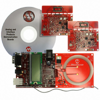
Description
BOARD DEMO PICTAIL MCP2030
Manufacturer
Microchip Technology
Type
Front Endr
Specifications of MCP2030DM-TPR
Frequency
125kHz
For Use With/related Products
MCP2030
Lead Free Status / RoHS Status
Not applicable / Not applicable
Lead Free Status / RoHS Status
Lead free / RoHS Compliant, Not applicable / Not applicable


MCP2030 Bidirectional Communication Demo Kit User’s Guide
DS51637A-page 12
3.2.5
The 125 kHz PWM from the PIC18F4680 is power boosted by the MOS FET driver
(TC4422). The PWM square pulse becomes a sine wave as the current passes through
the LC series resonant circuit formed by L1 and C2, C3, and C4 on the Base Station
Demo Board. The current that is passing through the L1 generates a magnetic field.
When this magnetic field transmitted from the Base Station Demo Board is passing
through the Transponder Demo Board’s antenna coil, it produces a voltage. This
voltage is detected by the MCP2030 LF front-end device and the information carried on
the voltage is processed by the PIC16F636 microcontroller on the transponder.
See Recommended Reading for more details of the near-field magnetic coupling
principles.
3.2.6
Power can be supplied through J1 power jack. The voltage should be in the range of
9 - 18 VDC with a current rating greater than 500 mA.
3.2.7
The bidirectional communication method between the Base Station Demo Board and
Transponder Demo Board is shown in
an LF command, receives the responses from the Transponder Demo Board, and dis-
plays the received responses on the LCD. The Base Station Demo Board repeats the
transmitting and receiving functions as long as its power supply is connected.
Figure 3-1
mat is shown in
included on the MCP2030 Bidirectional Communication Demo Kit CD ROM.
FIGURE 3-1:
AGC Stabilization Time
AGC Stabilization Time
High Duration
4 ms
125 kHz Low Frequency Command Initiator
Power
MCU FIRMWARE ALGORITHM
shows the LF command data format and waveform. The receiving data for-
Figure
500 ms
Gap
Base Station Demo Board LF Command Data Format.
Gap
3-5. The MCU firmware for the communication algorithm is
High Duration Low Duration
2 ms
Wake-Up Filter
Wake-Up Filter
Transmitting Data: LSB First
Figure
2 ms
2-2. The Base Station Demo Board sends
Command Type (3C)
+LF turns-on for 50 ms
= 1100 0011P
= LSB first of 3C (hex)
3C+Parity + Stop bit
Command Type
+ Continuous LF
Receiving Data: LSB First
Continuous LF Field
This allows the Transponder
to sample the RSSI data
© 2006 Microchip Technology Inc.
32 bit ID+RSSI+Parity Bits
Waiting for Response
(Parity bit per byte)
Stop bit
Related parts for MCP2030DM-TPR
Image
Part Number
Description
Manufacturer
Datasheet
Request
R

Part Number:
Description:
IC KEYLESS ENTRY AFE 14TSSOP
Manufacturer:
Microchip Technology
Datasheet:

Part Number:
Description:
IC KEYLESS ENTRY AFE 14SOIC
Manufacturer:
Microchip Technology
Datasheet:

Part Number:
Description:
IC KEYLESS ENTRY AFE 14DIP
Manufacturer:
Microchip Technology
Datasheet:
Part Number:
Description:
3D ANALOG TRANSPONDER (AFE), -40C to +125C, 14-PDIP, TUBE
Manufacturer:
Microchip Technology
Datasheet:

Part Number:
Description:
Three-channel Analog Front-end Device
Manufacturer:
Microchip Technology Inc.
Datasheet:
Part Number:
Description:
Manufacturer:
Microchip Technology Inc.
Datasheet:
Part Number:
Description:
Manufacturer:
Microchip Technology Inc.
Datasheet:
Part Number:
Description:
Manufacturer:
Microchip Technology Inc.
Datasheet:
Part Number:
Description:
Manufacturer:
Microchip Technology Inc.
Datasheet:
Part Number:
Description:
Manufacturer:
Microchip Technology Inc.
Datasheet:
Part Number:
Description:
Manufacturer:
Microchip Technology Inc.
Datasheet: