MCP2030DM-TPR Microchip Technology, MCP2030DM-TPR Datasheet - Page 20
MCP2030DM-TPR
Manufacturer Part Number
MCP2030DM-TPR
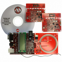
Description
BOARD DEMO PICTAIL MCP2030
Manufacturer
Microchip Technology
Type
Front Endr
Specifications of MCP2030DM-TPR
Frequency
125kHz
For Use With/related Products
MCP2030
Lead Free Status / RoHS Status
Not applicable / Not applicable
Lead Free Status / RoHS Status
Lead free / RoHS Compliant, Not applicable / Not applicable


MCP2030 Bidirectional Communication Demo Kit User’s Guide
DS51637A-page 16
3.3.6
The Transponder Demo Board has a Programming Connector (J1) for In-Circuit Serial
Programming™ (ICSP™). See
transmitter can therefore be re-programmed using the PICkit
removing the microcontroller from the board.
FIGURE 3-3:
3.3.7
The Transponder Demo Board is powered by a standard Lithium 3V coin cell battery.
3.3.8
When the Transponder Demo Board is powered on, the PIC16F636 (MCU) programs
the configuration registers of the MCP2030 and also the configuration register of the
MCP3421 (ADC). After these set-up procedures, the MCU enters a low-power sleep
mode while the MCP2030 is looking for a valid LF command. The MCU is waken-up by
the demodulated output from the MCP2030 or button switch event. If the MCU receives
a valid demodulated data from the MCP2030, then it transmits its 32 bit transponder ID
followed by the 16 bit received signal strength indicator (RSSI) data. If the MCU is
waken-up by a switch event (SW3 and SW4), it transmits the corresponding switch
event data. The data is always attached to the header (See
der ID is set to “04234567” and programmed in the EEPROM. The RSSI data is pro-
portional to the LF signal strength. Therefore, the RSSI data increases as the
Transponder Demo Board comes closer to the Base Station Demo Board. The Tran-
sponder Demo Board transmits each byte LSB first and also transmits a parity bit at
end of each byte. See
stream.
The MCU firmware is included in the MCP2030 Bidirectional Communication Demo Kit
CD ROM.
Figure 3-4
Programming of the Transponder
Power
Microcontroller Firmware Algorithm
shows the firmware flow chart.
J1 Programming Connector.
Figure 3-5
Figure 3-3
for more details of the Transponder Demo Board data
no connection
ICSPCLK
ICSPDAT
MCLR
V
for the J1 Programming Connector. The
V
CC
SS
1
2
3
4
5
6
© 2006 Microchip Technology Inc.
Figure
®
2 (or PICkit
3-5). The Transpon-
®
1) without
Related parts for MCP2030DM-TPR
Image
Part Number
Description
Manufacturer
Datasheet
Request
R

Part Number:
Description:
IC KEYLESS ENTRY AFE 14TSSOP
Manufacturer:
Microchip Technology
Datasheet:

Part Number:
Description:
IC KEYLESS ENTRY AFE 14SOIC
Manufacturer:
Microchip Technology
Datasheet:

Part Number:
Description:
IC KEYLESS ENTRY AFE 14DIP
Manufacturer:
Microchip Technology
Datasheet:
Part Number:
Description:
3D ANALOG TRANSPONDER (AFE), -40C to +125C, 14-PDIP, TUBE
Manufacturer:
Microchip Technology
Datasheet:

Part Number:
Description:
Three-channel Analog Front-end Device
Manufacturer:
Microchip Technology Inc.
Datasheet:
Part Number:
Description:
Manufacturer:
Microchip Technology Inc.
Datasheet:
Part Number:
Description:
Manufacturer:
Microchip Technology Inc.
Datasheet:
Part Number:
Description:
Manufacturer:
Microchip Technology Inc.
Datasheet:
Part Number:
Description:
Manufacturer:
Microchip Technology Inc.
Datasheet:
Part Number:
Description:
Manufacturer:
Microchip Technology Inc.
Datasheet:
Part Number:
Description:
Manufacturer:
Microchip Technology Inc.
Datasheet: