MCP2030DM-TPR Microchip Technology, MCP2030DM-TPR Datasheet - Page 18
MCP2030DM-TPR
Manufacturer Part Number
MCP2030DM-TPR
Description
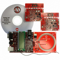
BOARD DEMO PICTAIL MCP2030
Manufacturer
Microchip Technology
Type
Front Endr
Specifications of MCP2030DM-TPR
Frequency
125kHz
For Use With/related Products
MCP2030
Lead Free Status / RoHS Status
Not applicable / Not applicable
Lead Free Status / RoHS Status
Lead free / RoHS Compliant, Not applicable / Not applicable


MCP2030 Bidirectional Communication Demo Kit User’s Guide
3.3
DS51637A-page 14
MCP2030 TRANSPONDER DEMO BOARD
3.3.1
3.3.2
The Transponder Demo Board uses a PIC16F636 microcontroller. This MCU is the
same device that is used inside the PIC16F639 which is a dual die package device
(PIC16F639 = PIC16F636 die + MCP2030 die in a single 20-pin package). The MCU
interfaces with the MCP2030 stand-alone analog front-end device for LF
communications and the MCP3421 delta-sigma analog-to-digital converter for RSSI
data conversion. When the MCU is first powered-up, it writes the MCP2030
configuration registers and also writes the configuration register of the MCP3421 ADC
(for 16 bit and one-shot mode).The MCP3421 stays in a low power standby mode after
one conversion. The MCU also stays in a low power sleep mode while the MCP2030
is looking for a valid LF command.
The MCU is waken up by the demodulated output from the MCP2030 or by a button
switch event (SW3 and SW4). The MCU decodes the demodulated output data from
the MCP2030. If the data is a valid command, it blinks the green LED (D6) and reads
the RSSI value by controlling the MCP3421 ADC. Once the RSSI value is acquired, the
MCU feeds the transponder ID and the RSSI data into the 433.92 MHz UHF
transmitter. The transmitted data from the UHF transmitter is detected by the RF
receiver in the Base Station Demo Board and the data is displayed on the LCD.
When a button switch is pressed, the MCU feeds a corresponding data into the UHF
transmitter. The red LED (D7) blinks each time the transponder transmits the UHF
response. The red LED also blinks when the transponder receives invalid data.
3.3.3
The MCP2030 detects the Base Station Demo Board’s LF command using three LF
antenna coils that are mounted on the Transponder Demo Board PCB. The Configura-
tion registers of the MCP2030 are configured by the MCU when the Transponder Demo
Board is powered up the first time, and are re-configured during operation. The MCU
controls the MCP2030 for two different outputs: (a) Demodulated data and (b)
Received Signal Strength Indicator output (RSSI). When it is detecting input signals,
the device is configured for the demodulated data output. Once the MCU finds a valid
LF command, then the MCU re-configures the MCP2030 for the RSSI output. In this
case, the MCP2030 outputs the RSSI current that is proportional to the LF input signal
LF Input Frequency:
LF Input Modulation Format:
Encoding Method:
Operating Voltage:
LF Input Sensitivity:
LF Detection Range:
Transmitting Frequency:
UHF Range:
Bidirectional Communication Range
Note 1:
2:
The minimum requirement for V
the V
stable.
Contact Microchip Technology Inc. for the device option with higher
than 3 mVpp sensitivity.
Technical Specifications
Microcontroller (PIC16F636)
Three-Input LF (125 kHz) Front-End (MCP2030)
DD
less than 2.7V, the ADC result of the RSSI value may not be
125 kHz
Amplitude Modulation
Pulse Width Modulation (PWM)
2 - 3.6V. See Note 1
~3 mVPP. See Note 2
Up to 3 meters
433.92 MHz
Up to ~ 20 meters
Up to 3 meters
DD
of the MCP3421ADC is 2.7V. For
© 2006 Microchip Technology Inc.
Related parts for MCP2030DM-TPR
Image
Part Number
Description
Manufacturer
Datasheet
Request
R

Part Number:
Description:
IC KEYLESS ENTRY AFE 14TSSOP
Manufacturer:
Microchip Technology
Datasheet:

Part Number:
Description:
IC KEYLESS ENTRY AFE 14SOIC
Manufacturer:
Microchip Technology
Datasheet:

Part Number:
Description:
IC KEYLESS ENTRY AFE 14DIP
Manufacturer:
Microchip Technology
Datasheet:
Part Number:
Description:
3D ANALOG TRANSPONDER (AFE), -40C to +125C, 14-PDIP, TUBE
Manufacturer:
Microchip Technology
Datasheet:

Part Number:
Description:
Three-channel Analog Front-end Device
Manufacturer:
Microchip Technology Inc.
Datasheet:
Part Number:
Description:
Manufacturer:
Microchip Technology Inc.
Datasheet:
Part Number:
Description:
Manufacturer:
Microchip Technology Inc.
Datasheet:
Part Number:
Description:
Manufacturer:
Microchip Technology Inc.
Datasheet:
Part Number:
Description:
Manufacturer:
Microchip Technology Inc.
Datasheet:
Part Number:
Description:
Manufacturer:
Microchip Technology Inc.
Datasheet:
Part Number:
Description:
Manufacturer:
Microchip Technology Inc.
Datasheet: