MCP2030DM-TPR Microchip Technology, MCP2030DM-TPR Datasheet - Page 19
MCP2030DM-TPR
Manufacturer Part Number
MCP2030DM-TPR
Description
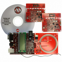
BOARD DEMO PICTAIL MCP2030
Manufacturer
Microchip Technology
Type
Front Endr
Specifications of MCP2030DM-TPR
Frequency
125kHz
For Use With/related Products
MCP2030
Lead Free Status / RoHS Status
Not applicable / Not applicable
Lead Free Status / RoHS Status
Lead free / RoHS Compliant, Not applicable / Not applicable


© 2006 Microchip Technology Inc.
MCP2030 Bidirectional Communication Demo Kit User’s Guide
strength. This current output is fed into a resistor and the voltage across the resistor is
fed into the MCP3421 ADC input pin. The converted16-bit ADC output is then fed into
the MCU.
The function of the MCP2030 is controlled by its configuration register settings. Highly
intelligent signal detection and response (bidirectional communications) is possible by
utilizing the MCP2030 configuration register settings. The user can easily change or
modify the included firmware for different settings of the MCP2030 configuration
registers for their own applications.
3.3.4
A 433.92 MHz UHF transmitter is used to transmit the Transponder Demo Board data
to the Base Station Demo Board. The UHF transmitter is based on a surface acoustic
wave (SAW) resonator. The transmitter is turned on during the high duration of the data
and off during the low duration of the bit data.
3.3.5
The Transponder Demo Board uses an MCP3421 ADC to convert the analog RSSI
output of the MCP2030 to digital data. The MCP3421 is a delta-sigma analog-to-digital
converter with 12, 14, 16, and 18 bit mode options. In this demo board, the converter
is configured for the 16 bit and one-shot mode. When the transponder is powered-up,
the MCU sends an I
conversion. After one conversion, the device stays in a low power standby mode.
During this mode, the device draws only about 1 µA. When the MCP2030 analog
front-end device receives a valid Base Station command, then the MCU sends an I
read command to the MCP3421 ADC for the analog-to-digital data conversion. At this
moment, the Base Station Demo Board transmits a continuous LF signal for about
50 ms allowing the MCP2030 to collect the RSSI values. The RSSI voltage across the
RSSI load resistor is fed into the MCP3421 input pin. After the MCU sends the I
command, it is waiting for the MCP3421 to complete the conversion by checking the
RDY bit of the MCP3421 output. In typical operation, it takes about 50 ms to complete
a 16 bit conversion. See
operation.
TABLE 3-1:
Port A
RA0
RA1
RA2
RA3
RA4
RA5
Port C
RC0
RC1
RC2
RC3
RC4
RC5
PORT Pin
Note:
Analog-to-Digital Converter (MCP3421)
The design and layout of this transmitter is not sufficient to ensure
compliance with EC or FCC regulations.
UHF Transmitter (433.92 MHz)
Switch 4
Switch 3
LFDATA Input from MCP2030, SPI SDIO for MCP2030
SPI SCLK Output for MCP2030
RF Active LED
SPI CS output for MCP2030
I
I
Valid LFDATA Input Indicator LED
RF Data Out
2
2
C SDA for MCP3421
C SCL for MCP3421
PIC16F636 I/O CONNECTIONS
2
C write command to the MCP3421 for one-shot mode and 16 bit
Figure 2-2
Function
and
Figure 2-3
for more information on the ADC
ICSP™ Data
ICSP Clock
ICSP MCLR
DS51637A-page 15
Notes
2
C read
2
C
Related parts for MCP2030DM-TPR
Image
Part Number
Description
Manufacturer
Datasheet
Request
R

Part Number:
Description:
IC KEYLESS ENTRY AFE 14TSSOP
Manufacturer:
Microchip Technology
Datasheet:

Part Number:
Description:
IC KEYLESS ENTRY AFE 14SOIC
Manufacturer:
Microchip Technology
Datasheet:

Part Number:
Description:
IC KEYLESS ENTRY AFE 14DIP
Manufacturer:
Microchip Technology
Datasheet:
Part Number:
Description:
3D ANALOG TRANSPONDER (AFE), -40C to +125C, 14-PDIP, TUBE
Manufacturer:
Microchip Technology
Datasheet:

Part Number:
Description:
Three-channel Analog Front-end Device
Manufacturer:
Microchip Technology Inc.
Datasheet:
Part Number:
Description:
Manufacturer:
Microchip Technology Inc.
Datasheet:
Part Number:
Description:
Manufacturer:
Microchip Technology Inc.
Datasheet:
Part Number:
Description:
Manufacturer:
Microchip Technology Inc.
Datasheet:
Part Number:
Description:
Manufacturer:
Microchip Technology Inc.
Datasheet:
Part Number:
Description:
Manufacturer:
Microchip Technology Inc.
Datasheet:
Part Number:
Description:
Manufacturer:
Microchip Technology Inc.
Datasheet: