DR-TRC105-434-EV RFM, DR-TRC105-434-EV Datasheet - Page 10
DR-TRC105-434-EV
Manufacturer Part Number
DR-TRC105-434-EV
Description
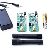
RF Modules & Development Tools TRC105 Evaluation Board 416-436 MHz
Manufacturer
RFM
Datasheet
1.DR-TRC105-315-DK.pdf
(27 pages)
Specifications of DR-TRC105-434-EV
Board Size
25.4 mm x 71.1 mm x 16.5 mm
Minimum Frequency
433.42 MHz
Supply Voltage (min)
2.7 V
Product
RF Modules
Maximum Frequency
434.42 MHz
Output Power
10 dBm
Antenna
SMA
Supply Voltage (max)
3.6 V
For Use With/related Products
TRC105
Lead Free Status / RoHS Status
Lead free / RoHS Compliant


When a DR-TRC105 radio board is initially power on, it is configured as follows:
The radio board is also initially configured in Receive Continuous Mode (see the
TRC105 datasheet for an explanation of continuous mode, buffered data mode, packet
data mode, etc.). In receive continuous mode, the MODE LED will be green. Receive
continuous mode allows the user to connect a modulated signal from a signal generator
source onto the board through a short, coaxial cable and verify the demodulated signal
with an oscilloscope through the DAT pin.
Briefly pressing the MODE button once configures the board into Transmit Continuous
Mode. The Mode LED will change color from green to yellow. This mode turns on the
transmitter. The frequency and output power may be verified on a spectrum analyzer. A
square-wave modulating signal may be applied to the DAT pin and modulation
observed on the spectrum analyzer.
Briefly pressing the MODE button again configures the board into Sleep Mode. The
Mode LED will turn off. By connecting an ammeter across the terminals of J1, with the
jumper removed, the user can verify the very low sleep current of the TRC105 device.
As shown in Figure 11, potentiometer R7 can be used to adjust the transmit power
level. To increase the output power, rotate the potentiometer screw clockwise. To
decrease the power, rotate the potentiometer screw counterclockwise. The transmit
power is divided into 8 levels. Adjusting R7 adjusts the voltage level to the A-to-D
converter (ADC) in the host microcontroller. The microcontroller periodically samples R7
for a change, and updates the transmit power register when it detects a change in
voltage level. Each time the microprocessor updates the transmit power register the SPI
LED D2 will flash indicating an SPI write.
www.RFM.com
©2009-2010 by RF Monolithics, Inc.
Operating Frequency:
Power: +10 dBm
Frequency Deviation: ±50 kHz
Data Rate: 25 kb/s
Receiver Baseband Bandwidth: 100 kHz
DR-TRC105-304-EV
DR-TRC105-315-EV
DR-TRC105-345-EV
DR-TRC105-372-EV
DR-TRC105-390-EV
DR-TRC105-403-EV
DR-TRC105-434-EV
DR-TRC105-450-EV
Technical support +1.800.704.6079
E-mail:
303.825 MHz
315.000 MHz
345.000 MHz
372.250 MHz
390.000 MHz
403.500 MHz
433.920 MHz
450.000 MHz
info@rfm.com
DR-TRC105-DK - 04/05/10
Page 10 of 27
Related parts for DR-TRC105-434-EV
Image
Part Number
Description
Manufacturer
Datasheet
Request
R

Part Number:
Description:
DEV KIT TRC105
Manufacturer:
RFM
Datasheet:

Part Number:
Description:
DEV KIT TRC105
Manufacturer:
RFM
Datasheet:

Part Number:
Description:
DEV KIT TRC105
Manufacturer:
RFM
Datasheet:

Part Number:
Description:
DEV KIT TRC105
Manufacturer:
RFM
Datasheet:

Part Number:
Description:
DEV KIT TRC105
Manufacturer:
RFM
Datasheet:

Part Number:
Description:
DEV KIT TRC105
Manufacturer:
RFM
Datasheet:

Part Number:
Description:
DEV KIT TRC105
Manufacturer:
RFM
Datasheet:

Part Number:
Description:
DEV KIT TRC105
Manufacturer:
RFM
Datasheet:

Part Number:
Description:
RF Modules & Development Tools TRC105 Evaluation Board 447-451 MHz
Manufacturer:
RFM
Datasheet:
Part Number:
Description:
RF Modules & Development Tools TRC105 Evaluation Board 365-381 MHz
Manufacturer:
RFM
Datasheet:

Part Number:
Description:
WiFi / 802.11 Modules 2.4 and 5.8GHz + BT
Manufacturer:
RFM
Datasheet:

Part Number:
Description:
10-Terminal Ceramic Surface-Mount Case 7 x 5 mm Nominal Footprint
Manufacturer:
RFM [RF Monolithics, Inc]
Datasheet:
Part Number:
Description:
QUAD-BAND GSM850/GSM/DCS/PCS POWER AMP MODULE
Manufacturer:
RFM [RF Monolithics, Inc]
Datasheet:
Part Number:
Description:
402 to 405 MHz Medical Band Front-end Filter
Manufacturer:
RFM [RF Monolithics, Inc]
Datasheet: