DR-TRC105-434-EV RFM, DR-TRC105-434-EV Datasheet - Page 16
DR-TRC105-434-EV
Manufacturer Part Number
DR-TRC105-434-EV
Description
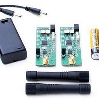
RF Modules & Development Tools TRC105 Evaluation Board 416-436 MHz
Manufacturer
RFM
Datasheet
1.DR-TRC105-315-DK.pdf
(27 pages)
Specifications of DR-TRC105-434-EV
Board Size
25.4 mm x 71.1 mm x 16.5 mm
Minimum Frequency
433.42 MHz
Supply Voltage (min)
2.7 V
Product
RF Modules
Maximum Frequency
434.42 MHz
Output Power
10 dBm
Antenna
SMA
Supply Voltage (max)
3.6 V
For Use With/related Products
TRC105
Lead Free Status / RoHS Status
Lead free / RoHS Compliant


Firmware should be loaded and tested with the interface board powered on. The C
source code for the firmware shipped in the development kit is included on the CD for
reference.
Radio Board Interface Connector
Figure 17 shows the pin numbering detail of connector J2 on the edge of the DR-
TRC105 radio boards. Figure 17 can be used with the schematics in the last section of
this manual to design a custom application interface for the radio boards. Note that all
signal levels into and out of this connector are nominally 3 volt logic level. Attempting to
use RS232 signal levels to directly interface the radio board can damage it.
Figure 17 - DR-TRC105 Radio Board Connector Detail
Development Kit Documentation
The schematics of each radio board and the interface board with the top assembly
views are provided on the following pages. Also see the RFIC Design Assistant utility
software and related User’s Guide, the DR-TRC105-EV Evaluation Kit User’s Guide,
and the TRC105 Data Sheet. The latest versions of the Data Sheet, User’s Guides, and
the RFIC Design Assistant utility software can be downloaded from RFM’s web site,
www.rfm.com.
www.RFM.com
Technical support +1.800.704.6079
Page 16 of 27
©2009-2010 by RF Monolithics, Inc.
E-mail:
info@rfm.com
DR-TRC105-DK - 04/05/10
Related parts for DR-TRC105-434-EV
Image
Part Number
Description
Manufacturer
Datasheet
Request
R

Part Number:
Description:
DEV KIT TRC105
Manufacturer:
RFM
Datasheet:

Part Number:
Description:
DEV KIT TRC105
Manufacturer:
RFM
Datasheet:

Part Number:
Description:
DEV KIT TRC105
Manufacturer:
RFM
Datasheet:

Part Number:
Description:
DEV KIT TRC105
Manufacturer:
RFM
Datasheet:

Part Number:
Description:
DEV KIT TRC105
Manufacturer:
RFM
Datasheet:

Part Number:
Description:
DEV KIT TRC105
Manufacturer:
RFM
Datasheet:

Part Number:
Description:
DEV KIT TRC105
Manufacturer:
RFM
Datasheet:

Part Number:
Description:
DEV KIT TRC105
Manufacturer:
RFM
Datasheet:

Part Number:
Description:
RF Modules & Development Tools TRC105 Evaluation Board 447-451 MHz
Manufacturer:
RFM
Datasheet:
Part Number:
Description:
RF Modules & Development Tools TRC105 Evaluation Board 365-381 MHz
Manufacturer:
RFM
Datasheet:

Part Number:
Description:
WiFi / 802.11 Modules 2.4 and 5.8GHz + BT
Manufacturer:
RFM
Datasheet:

Part Number:
Description:
10-Terminal Ceramic Surface-Mount Case 7 x 5 mm Nominal Footprint
Manufacturer:
RFM [RF Monolithics, Inc]
Datasheet:
Part Number:
Description:
QUAD-BAND GSM850/GSM/DCS/PCS POWER AMP MODULE
Manufacturer:
RFM [RF Monolithics, Inc]
Datasheet:
Part Number:
Description:
402 to 405 MHz Medical Band Front-end Filter
Manufacturer:
RFM [RF Monolithics, Inc]
Datasheet: