DR-TRC105-434-EV RFM, DR-TRC105-434-EV Datasheet - Page 5
DR-TRC105-434-EV
Manufacturer Part Number
DR-TRC105-434-EV
Description
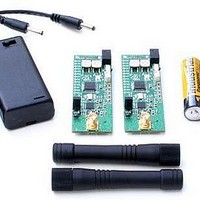
RF Modules & Development Tools TRC105 Evaluation Board 416-436 MHz
Manufacturer
RFM
Datasheet
1.DR-TRC105-315-DK.pdf
(27 pages)
Specifications of DR-TRC105-434-EV
Board Size
25.4 mm x 71.1 mm x 16.5 mm
Minimum Frequency
433.42 MHz
Supply Voltage (min)
2.7 V
Product
RF Modules
Maximum Frequency
434.42 MHz
Output Power
10 dBm
Antenna
SMA
Supply Voltage (max)
3.6 V
For Use With/related Products
TRC105
Lead Free Status / RoHS Status
Lead free / RoHS Compliant


The power switch shown in Figure 2 connects the output of the 3 volt regulator on the
interface board to the POWER ON LED, the serial communication interface circuitry and
the radio board. Note that there is a small current draw from the regulator when the
power switch is in the off position, and this will eventually discharge a 9 volt battery if it
is left installed.
The radio RESET button on the interface module allows the user to reset the radio
board to a know state from any mode the radio board is in.
Figure 4 - DR-TRC105-DK Interface Board Serial Connectors
Figure 4 shows the serial communication connectors on the interface board. The kit
includes two USB 2.0 A/B cables for connection to a PC. When a USB cable is plugged
into an interface board, it automatically disables the RS232 interface circuitry. Note that
the interface board is not designed to powered from the USB interface, so DC power
must be supplied separately as discussed above. The kit CD includes the PC drivers
needed to make the interface board USB connection appear as a virtual COM port.
Refer to the USB Virtual COM Ports section of the RFIC Design Assistant User’s Guide
on the CD for driver installation details.
To configure the interface board for RS232 operation, remove the serial jumpers shown
in Figure 4. Use a 9-pin “external modem cable” (straight through, not null modem) to
connect the interface board to the PC.
The left panel in Figure 5 shows USB operation, the right panel shows RS232
operation. Note the serial jumpers have been removed for RS232 operation.
www.RFM.com
Technical support +1.800.704.6079
Page 5 of 27
©2009-2010 by RF Monolithics, Inc.
E-mail:
info@rfm.com
DR-TRC105-DK - 04/05/10
Related parts for DR-TRC105-434-EV
Image
Part Number
Description
Manufacturer
Datasheet
Request
R

Part Number:
Description:
DEV KIT TRC105
Manufacturer:
RFM
Datasheet:

Part Number:
Description:
DEV KIT TRC105
Manufacturer:
RFM
Datasheet:

Part Number:
Description:
DEV KIT TRC105
Manufacturer:
RFM
Datasheet:

Part Number:
Description:
DEV KIT TRC105
Manufacturer:
RFM
Datasheet:

Part Number:
Description:
DEV KIT TRC105
Manufacturer:
RFM
Datasheet:

Part Number:
Description:
DEV KIT TRC105
Manufacturer:
RFM
Datasheet:

Part Number:
Description:
DEV KIT TRC105
Manufacturer:
RFM
Datasheet:

Part Number:
Description:
DEV KIT TRC105
Manufacturer:
RFM
Datasheet:

Part Number:
Description:
RF Modules & Development Tools TRC105 Evaluation Board 447-451 MHz
Manufacturer:
RFM
Datasheet:
Part Number:
Description:
RF Modules & Development Tools TRC105 Evaluation Board 365-381 MHz
Manufacturer:
RFM
Datasheet:

Part Number:
Description:
WiFi / 802.11 Modules 2.4 and 5.8GHz + BT
Manufacturer:
RFM
Datasheet:

Part Number:
Description:
10-Terminal Ceramic Surface-Mount Case 7 x 5 mm Nominal Footprint
Manufacturer:
RFM [RF Monolithics, Inc]
Datasheet:
Part Number:
Description:
QUAD-BAND GSM850/GSM/DCS/PCS POWER AMP MODULE
Manufacturer:
RFM [RF Monolithics, Inc]
Datasheet:
Part Number:
Description:
402 to 405 MHz Medical Band Front-end Filter
Manufacturer:
RFM [RF Monolithics, Inc]
Datasheet: