DR-TRC105-434-EV RFM, DR-TRC105-434-EV Datasheet - Page 4
DR-TRC105-434-EV
Manufacturer Part Number
DR-TRC105-434-EV
Description
RF Modules & Development Tools TRC105 Evaluation Board 416-436 MHz
Manufacturer
RFM
Datasheet
1.DR-TRC105-315-DK.pdf
(27 pages)
Specifications of DR-TRC105-434-EV
Board Size
25.4 mm x 71.1 mm x 16.5 mm
Minimum Frequency
433.42 MHz
Supply Voltage (min)
2.7 V
Product
RF Modules
Maximum Frequency
434.42 MHz
Output Power
10 dBm
Antenna
SMA
Supply Voltage (max)
3.6 V
For Use With/related Products
TRC105
Lead Free Status / RoHS Status
Lead free / RoHS Compliant


Figure 2 - DR-TRC105-DK Interface Board Connectors and Controls
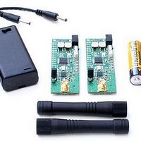
Figure 2 shows the locations of the interface board DC power connectors, user controls
and LED indicators. Normally an interface board is powered from one of the 4.5 volt
universal wall-plug power supplies provided in the development kit, as shown in the left
panel of Figure 3. For roaming range testing and field testing, the interface board can be
powered from a 9 volt battery as shown in the right panel of Figure 3. Note - do not
install a 9 volt battery while the interface board is connected to the wall-plug power
supply. Use only one power source at a time. Power input pins are also provided for
connection to a regulated 4.5 to 12 volt lab supply. When connecting to these pins, take
care with the polarity. The pin closest to the power connector is the positive input.
Figure 3 - Power Options
www.RFM.com
Technical support +1.800.704.6079
Page 4 of 27
©2009-2010 by RF Monolithics, Inc.
E-mail:
info@rfm.com
DR-TRC105-DK - 04/05/10
Related parts for DR-TRC105-434-EV
Image
Part Number
Description
Manufacturer
Datasheet
Request
R

Part Number:
Description:
DEV KIT TRC105
Manufacturer:
RFM
Datasheet:

Part Number:
Description:
DEV KIT TRC105
Manufacturer:
RFM
Datasheet:

Part Number:
Description:
DEV KIT TRC105
Manufacturer:
RFM
Datasheet:

Part Number:
Description:
DEV KIT TRC105
Manufacturer:
RFM
Datasheet:

Part Number:
Description:
DEV KIT TRC105
Manufacturer:
RFM
Datasheet:

Part Number:
Description:
DEV KIT TRC105
Manufacturer:
RFM
Datasheet:

Part Number:
Description:
DEV KIT TRC105
Manufacturer:
RFM
Datasheet:

Part Number:
Description:
DEV KIT TRC105
Manufacturer:
RFM
Datasheet:

Part Number:
Description:
RF Modules & Development Tools TRC105 Evaluation Board 447-451 MHz
Manufacturer:
RFM
Datasheet:
Part Number:
Description:
RF Modules & Development Tools TRC105 Evaluation Board 365-381 MHz
Manufacturer:
RFM
Datasheet:

Part Number:
Description:
WiFi / 802.11 Modules 2.4 and 5.8GHz + BT
Manufacturer:
RFM
Datasheet:

Part Number:
Description:
10-Terminal Ceramic Surface-Mount Case 7 x 5 mm Nominal Footprint
Manufacturer:
RFM [RF Monolithics, Inc]
Datasheet:
Part Number:
Description:
QUAD-BAND GSM850/GSM/DCS/PCS POWER AMP MODULE
Manufacturer:
RFM [RF Monolithics, Inc]
Datasheet:
Part Number:
Description:
402 to 405 MHz Medical Band Front-end Filter
Manufacturer:
RFM [RF Monolithics, Inc]
Datasheet: