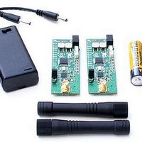
DR-TRC105-434-EV RFM, DR-TRC105-434-EV Datasheet - Page 9

DR-TRC105-434-EV
Manufacturer Part Number
DR-TRC105-434-EV
Description
RF Modules & Development Tools TRC105 Evaluation Board 416-436 MHz
Manufacturer
RFM
Datasheet
1.DR-TRC105-315-DK.pdf
(27 pages)
Specifications of DR-TRC105-434-EV
Board Size
25.4 mm x 71.1 mm x 16.5 mm
Minimum Frequency
433.42 MHz
Supply Voltage (min)
2.7 V
Product
RF Modules
Maximum Frequency
434.42 MHz
Output Power
10 dBm
Antenna
SMA
Supply Voltage (max)
3.6 V
For Use With/related Products
TRC105
Lead Free Status / RoHS Status
Lead free / RoHS Compliant
Radio Board Details
The DR-TRC105 radio board LED indicator names and locations are shown in Figure
10. Table 2 summarizes the functions of the DR-TRC105 radio board connectors, user
controls and LED indicators.
Component
I/O Connector
Battery Connector
Battery Power Switch
Mode Switch
Range Switch
TX Power Adj Pot
Antenna Connector
Current Monitor Pins
Serial/PLL LED
TRC105 SPI LED
Packet Error LED
Good Packet LED
MODE LED
RANGE LED
Low Battery LED
www.RFM.com
©2009-2010 by RF Monolithics, Inc.
Table 2 - DR-TRC105 Radio Board Connector, Control and Indicator Functions
Designator
Figure 10 - DR-TRC105 Radio Board LED Indicators
RF-IO
SW1
SW2
SW3
R7
D1
D2
D3
D4
D5
D6
D7
J2
J1
J3
Technical support +1.800.704.6079
20-pin connector for power and logic signal I/O (bottom of board)
Radio board “battery” power connector, 2.7 to 3.6 volts
On/off switch, in line with battery connector
Used to set the radio mode
Used to set up range testing and data terminal functions
Transmitter power adjustment potentiometer
50 ohm antenna connector, standard SMA
Remove jumper from these pins to measure TRC105 current
Yellow LED blinks to indicate serial activity with external host
Yellow LED blinks to indicate SPI activity to/from the TRC105
Red LED blinks to indicate received packet failed CRC check
Green LED blinks to indicate received packet passed CRC check
Green/yellow LED color indicates mode of operation
Yellow LED blinks to indicate range test or data terminal operation
Red LED illuminated to indicate low battery (must be configured)
E-mail:
info@rfm.com
Function
DR-TRC105-DK - 04/05/10
Page 9 of 27


