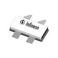
PTFB241402F V1 R250 Infineon Technologies, PTFB241402F V1 R250 Datasheet

PTFB241402F V1 R250
Specifications of PTFB241402F V1 R250
Related parts for PTFB241402F V1 R250
PTFB241402F V1 R250 Summary of contents
Page 1
Confidential, Limited Internal Distribution High Power RF LDMOS Field Effect Transistor 140 W, 2300 – 2400 MHz Description The PTFB241402F integrates two LDMOS FETs into one open-cavity ceramic package designed for cellular amplifier applications in the 2300 to ...
Page 2
... Operating Gate Voltage Gate Leakage Current Maximum Ratings Parameter Drain-Source Voltage Gate-Source Voltage Junction Temperature Storage Temperature Range Thermal Resistance (T = 70°C, 140 CASE Ordering Information Type and Version Package Outline PTFB241402F V1 H-37248-4 PTFB241402F V1 R250 H-37248-4 Data Sheet Conditions Symbol (BR)DSS ...
Page 3
Confidential, Limited Internal Distribution Typical Performance (data taken in a production test fixture) CW Performance, Single Side 660 18.0 17.0 16.0 Gain 15.0 Efficiency 14 ...
Page 4
Confidential, Limited Internal Distribution Typical Performance (cont.) Two-tone Performance at Selected Frequencies, Single Side 660 mA, 1 MHz Spacing 2320 MHz Efficiency 40 2350 MHz 2380 MHz 30 IMD3 20 10 ...
Page 5
Confidential, Limited Internal Distribution Broadband Circuit Impedance Z Source G G 2320 MHz 2380 MHz Data Sheet Z Load D Frequency MHz S 2320 2350 2380 D Z Load PTFB241402F Z Source W Z Load W R ...
Page 6
Confidential, Limited Internal Distribution Reference Circuit This reference circuit is designed to test only one side at a time. This block diagram shows the configuration for testing Side 2. To test Side 1, move capacitors C807 and C901 to close ...
Page 7
Confidential, Limited Internal Distribution Reference Circuit (cont.) TL936 TL943 V DD TL929 TL930 TL931 TL924 TL916 TL946 Pin D1 2 DRAIN DUT SIDE 1 TL925 TL945 Pin D2 2 DRAIN DUT 3 SIDE 2 TL903 2 TL905 1 TL904 TL927 ...
Page 8
Confidential, Limited Internal Distribution Reference Circuit (cont.) Description DUT PTFB241402F PCB 0.508 mm [.020"] thick, Electrical Characteristics at 2380 MHz Transmission Electrical Line Characteristics Input 0.114 l, 35.71 W TL801 TL802, TL838 0.005 l, 51.98 W TL803, TL804 TL805 0.063 ...
Page 9
Confidential, Limited Internal Distribution Reference Circuit (cont.) Electrical Characteristics at 2380 MHz Transmission Electrical Line Characteristics Output TL901, TL902 0.077 l, 28.85 W 0.031 l, 28.85 W TL903 TL904 0.036 l, 28.85 W TL905, TL931 0.019 l, 28.85 W 0.078 ...
Page 10
Confidential, Limited Internal Distribution Reference Circuit (cont.) Circuit Assembly Information Test Fixture Part No. LTN/PTFB241402F Find Gerber files for this test fixture on the Infineon Web site at R802 C803 S2 S1 R803 R805 C808 C806 R807 S3 R809 PTFB241402_IN_01 ...
Page 11
... Lead connections for PTFB241402F Data Sheet Suggested Manufacturer Digi-Key Digi-Key ATC ATC Digi-Key Digi-Key Digi-Key Digi-Key Digi-Key Digi-Key Digi-Key National Semiconductor Digi-Key Murata Infineon Technologies ATC Digi-Key ATC Digi-Key Murata Gate Drain G1 D1 Gate Drain G2 D2 Source (flange 7248 - 4_pd_ 0 3- 23- 2 010 ...
Page 12
Confidential, Limited Internal Distribution Package Outline Specifications 2X 45° X 2.720 2X 4.826±0.510 [.190±0.020] LID 9.398 FLANGE 9.779 [.370] [.385] SPH 1.575 [.062] +0.254 3.759 -0. 127 +0. 010 [ .148 ] -0.005 Diagram Notes—unless otherwise specified: 1. Interpret dimensions ...
Page 13
... Infineon Technologies components may be used in life-support devices or systems only with the express written approval of Infineon Technologies failure of such components can reasonably be expected to cause the failure of that life-support device or system or to affect the safety or effectiveness of that device or system. Life support devices or systems are intended to be implanted in the human body or to support and/or maintain and sustain and/or protect human life ...


