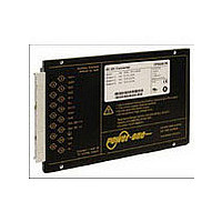
CP2101-9R POWER ONE, CP2101-9R Datasheet - Page 14

CP2101-9R
Manufacturer Part Number
CP2101-9R
Description
Manufacturer
POWER ONE
Type
Step Downr
Datasheet
1.CP2101-9R.pdf
(25 pages)
Specifications of CP2101-9R
Input Voltage
48V
Screening Level
Commercial
Operating Temperature Min Deg. C
-40C
Operating Temperature Max Deg. C
71C
Product Length (mm)
164mm
Product Depth (mm)
111mm
Product Height (mm)
19.8mm
Mounting Style
Din-Rail
Pin Count
15
Number Of Outputs
2
Lead Free Status / RoHS Status
Not Compliant
Auxiliary Functions
Primary Inhibit (Remote On / Off)
The inhibit input enables (logic low, pull down) or disables
(logic high, pull up or open-circuit) the output, if a logic signal
(TTL, CMOS) is applied. In systems consisting of several
converters, this feature may be used to control the activation
sequence by logic signals or to enable the power source to
start up, before full load is applied.
Table 6: Inhibit characteristics
The output response after enabling or disabling the output by
the inhibit input is shown in the figure below. See also Input
Data.
Fig. 17
Output response as a function of V
inhibit control
Output Voltage Adjust of V
The converters offer adjust of the voltage of powertrain 1.
Powertrain 2 can not be adjusted. The programming is
performed either by an external control voltage V
external resistor R
is limited to the values given in the table Electrical Output
Data.
With double output powertrains, both outputs are influenced
by the R-input setting simultaneously.
BCD20010-G Rev AC, 26-Aug-09
Characteristic
V
I
Note: If this function is not used, pin 28 must be connected with
pin 32, otherwise the internal logic will disable the output.
Note: With open R input, V
Note: With open R input, V
inh
inh
V
1.01
0.99
Note: The secondary referenced inhibit function, refers to the
description of option i.
i min
V
0.1
2.4
0.8
0
V
Inhibit
Voltage
Inhibit current
o
0
/V
inh
V
o nom
i
[V]
V
V
t
d on
o
o
= on
= off
t
r
1
or R
Conditions
V
T
V
V
V
®
C min
2
i min
inh
inh
inh
, connected to the R-input. Trimming
o
o
= – 50 V
= 0 V
= 50 V
= V
= V
– V
– T
o nom
o nom
i max
C max
o1
.
.
and V
i
(on/off switching) or
min
– 50
2.4
o 4
–1000
typ
–40
t
900
f
max
0.8
50
06159a
ext
t
t
t
or an
Unit
μA
Page 14 of 25
V
a) Adjustment by means of an external voltage:
Fig. 18
Output adjust of V
other outputs are not influenced.
b) Adjustment by means of an external resistor:
Fig. 19
Output adjust of V
outputs are not influenced.
Caution: To prevent damage, V
negative.
Note: If output voltages are set higher than V
currents should be reduced accordingly, so that the maximum
specified output power is not exceeded.
Note: R inputs of n converters with paralleled outputs may be
connected together, but if only one external resistor is used, its
value should be R
V
The adjust resistor R
S– (14) to set V
connected between pin 16 and S+ (12) to set V
ext
≈ –––
V
2.72
90 – 194 Watt DC-DC Converters
o nom
––––
Double-
output
powertrain
Double-
output
powertrain
i
Vi+
Vi–
i
Vi+
Vi–
V
o1
1
o1
o1
–– – 0.28 V
/n or R
and V
and V
o
< V
JM034
JM035
1
2
Vo1+
Vo4+
Vo4+
Vo1–
Vo4–
Vo1+
Vo1–
Vo4–
o4
/n.
o4
is connected between pin 16 and
o nom
R1
R1
S+
S+
S–
S–
with an external voltage V
using R
ext
16
16
, or the adjust resistor R
P Series Data Sheet
should not exceed 20 V, nor be
+
V
ext
1
–
or R
R
1
2
. The other
www.power-one.com
Load 4
Load 1
Load 4
R
o nom
2
Load 1
, the output
o
> V
ext
o nom
. The
2
.
is


