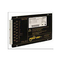
CP2101-9R POWER ONE, CP2101-9R Datasheet - Page 23

CP2101-9R
Manufacturer Part Number
CP2101-9R
Description
Manufacturer
POWER ONE
Type
Step Downr
Datasheet
1.CP2101-9R.pdf
(25 pages)
Specifications of CP2101-9R
Input Voltage
48V
Screening Level
Commercial
Operating Temperature Min Deg. C
-40C
Operating Temperature Max Deg. C
71C
Product Length (mm)
164mm
Product Depth (mm)
111mm
Product Height (mm)
19.8mm
Mounting Style
Din-Rail
Pin Count
15
Number Of Outputs
2
Lead Free Status / RoHS Status
Not Compliant
Description of Options
Option D: Out OK Monitor
Option D monitors the state of the output error amplifiers on
both power trains rather than the input voltage, output
voltage, or the current limit. It signals a fault, when one of the
error amplifiers reaches its limit, which means that at least
one output voltage is not within its regulation limits. This
could occur, because the input voltage is below the
minimum level or the load current is too high. This function is
not adjustable.
A galvanically isolated open-collector output generates the
“Out OK” signal. The circuit monitors simultaneously that
The open collector is conducting, if the monitored conditions
are fulfilled.
This option is located on a subassembly allowing special
circuit design on customer request.
Dimensioning of resistor value R
Table 16: Output OK data
Fig. 25
Output OK circuit (option D)
Option T: Active Current Sharing
For 3.3 V and 5.1 V outputs only. The current share facility
should be used, where several converters are operated in
parallel. Examples could be high reliability n+1 redundant
systems or systems providing higher output power.
Using this feature reduces the stress of individual
converters and improves the reliability of the system.
Interconnection of the current sharing pins T or T1 causes
the converters to share their output currents evenly.
BCD20010-G Rev AC, 26-Aug-09
• the input voltage is present - same logic as LED “In OK”
• the output voltages are within their limits - same logic as
Characteristics / Conditions
V
I
Caution: The Out OK circuit is protected by a Zener diode. To
prevent damage, the applied current I
mA. The Zener diode should not be exposed to more than 0.25 W.
OK
OK
LED(s) “Out OK”.
Out OK voltage
Output good, I
Out OK current
Output out of range, V
monitoring
Output
circuit
OK
< 50 mA
®
OK
06151a
20 V
< 18 V
22
24
p
OK
≥ ––––––
I
OK
should be limited to ±50
50 mA
min
V
p
V
OK
+
typ max
0.8
V
R
p
p
1.5
25
Out OK+
Out OK–
Unit
Page 23 of 25
μA
V
In redundant systems, the outputs of the converters are
decoupled by ORing diodes. Consequently, a failure of one
converter will not lead to a system failure.
Since the voltage on the T or T1 pin is referenced to the
sense pin S–, the installer must ensure that the S– pins of all
parallel converters are at the same electrical potential and
that there are no voltage drops across the connection lines
between these pins.
Double-output converters with outputs connected in series
can also be paralleled with current sharing, if pins Vo1– of all
converters are connected together; sefig. 10.
If the output voltages of parallel connected single-output
converters are programmed to a voltage other than V
means of the R pin, the outputs should be adjusted
individually within a tolerance of ±1%.
Option i: Secondary-Referenced Inhibit
The inhibit function is located on the primary side. Option i
gives the possibility of an inhibit function on the secondary
side using two galvanically isolated pins i+ and i–. The
power supply may be inhibited from either the input or the
output inhibit logic. The inhibit is enabled or disabled by a
logic signal (TTL, CMOS, etc). Output enabled: Logic low
(<0.8 V) Output inhibited: Logic high (>2.4 V).
This option excludes Opt.-D.
Opt.-i is located on a subassembly allowing special circuit
design on customer request.
The secondary inhibit is fully floating with operational
insulation to the secondary circuits (which is not sufficient to
be used as a primary to secondary insulation).
The input is CMOS compatible, and the level should not
exceed 5 V. The internal pull-up (to an internal 5 V supply) is
10 kOhms. We suggest connecting i– to S–; otherwise the
inhibit potential will be undefined.
Option B1 and B3: Heat Sink
The converter is fitted with an additional heat sink.
Option G
RoHS compliant for all six substances.
Table 17: Thermal resistance case to ambient (approx.
values)
Case
Standard, 160 mm long
Case, 220 mm long
Option B1
Option B3
Note: Option T is only available for 3.3 V or 5.1 V single-output
power trains and only for output 1. In dual- or triple-output
models, option T1 influences only output 1. In addition, the second
power train has no R input (since no pin is left for that function).
1
Customer-specific models
90 – 194 Watt DC-DC Converters
1
Thermal resistance Thickness of case
1.4 K/W
1.4 K/W
1.2 K/W
1.6 K/W
P Series Data Sheet
www.power-one.com
< 20 mm
< 20 mm
< 40 mm
< 50 mm
o nom
by


