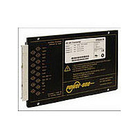
CP2101-9R POWER ONE, CP2101-9R Datasheet - Page 16

CP2101-9R
Manufacturer Part Number
CP2101-9R
Description
Manufacturer
POWER ONE
Type
Step Downr
Datasheet
1.CP2101-9R.pdf
(25 pages)
Specifications of CP2101-9R
Input Voltage
48V
Screening Level
Commercial
Operating Temperature Min Deg. C
-40C
Operating Temperature Max Deg. C
71C
Product Length (mm)
164mm
Product Depth (mm)
111mm
Product Height (mm)
19.8mm
Mounting Style
Din-Rail
Pin Count
15
Number Of Outputs
2
Lead Free Status / RoHS Status
Not Compliant
BCD20010-G Rev AC, 26-Aug-09
Electromagnetic Compatibility (EMC)
A metal oxide VDR together with an input fuse and a
symmetrical input filter form an effective protection against
Electromagnetic Immunity
Table 9: Immunity type tests
Phenomenon
Supply related
surge
Direct transients
Indirect coupled
transients
Electrostatic
discharge
(to case)
Electromagnetic
field
Electrical fast
transients/burst
Surges
Conducted
disturbances
1
2
3
4
5
6
7
8
9
10
i = input, o = output, c = case.
A = Normal operation, no deviation from specs, B = Temporary deviation from specs possible.
Measured with an external input capacitor specified in table 4. Complies with EN 50121-3-2:2006 table 7.3 and EN 50121-4:2006 table 2.3.
Corresponds to EN 50155:2001, waveform A, and EN 50121-3-2:2000 table 7.2.
Corresponds to EN 50155:2001, waveform B.
Exceeds EN 50121-3-2:2006 table 9.3 and EN 50121-4:2006 table 1.4.
Corresponds to EN 50121-3-2:2006 table 9.1 and exceeds EN 50121-4:2006 table 1.1.
Corresponds to EN 50121-3-2:2006 table 9.2 and EN 50121-4:2006 table 1.2 (compliance with digital mobile phones).
Corresponds to EN 50121-3-2:2006 table 7.2 and EN 50121-4:2006 table 2.2.
Corresponds to EN 50121-3-2:2006 table 7.1 and EN 50121-4:2006 table 3.1 (radio frequency common mode).
RIA 12
IEC/EN
Standard
EN 50155
RIA 12
EN 50155:
IEC/EN
61000-4-2
IEC/EN
61000-4-3
61000-4-4:
2004
IEC/EN
61000-4-5
IEC/EN
61000-4-6
®
1995
Level
3
G
D
4
x
3
3
2
B
H
L
4
4
8
10
6
7
9
3
3
4
5
capacit. (fig. 10), o/c
direct coupl. (fig. 9) ±2000 V
contact discharge
–o/c, +o/–o, –o/–i
i, o, signal wires
air discharge
+i/c, –i/c,+i/– i
Coupling
–i/c, +i/–i
+i/c, – i/c
antenna
antenna
mode
+i/– i
+i/–i
1
Page 16 of 25
(140 dBμV)
±2000 V
15000 V
±4000 V
±2000 V
1.5 • V
1.4 • V
1000 V
applied
1800 V
8400 V
1800 V
8400 V
8000 V
10 VAC
20 V/m
20 V/m
Value
10 Vm
5 V/m
batt
batt
high input transient voltages, which typically occur in most
installations,
applications. The Q Series has been successfully tested to
the following specifications:
p
p
p
p
p
p
p
p
3
p
p
p
9
3
bursts of 5/50 ns,
5 kHz over 15 ms,
burst period: 300
80% AM, 1 kHz
80% AM, 1 kHz
Waveform
0.05/ 0.1 μs
0.05/0.1 μs
0.1/1/0.1 s
1.2/50 μs
AM 80%
5/50 μs
5/50 μs
1/50 ns
1 kHz
ms
90 – 194 Watt DC-DC Converters
but
Source
imped.
especially
100 Ω
330 Ω
150 Ω
0.2 Ω
50 Ω
12 Ω
1 Ω
5 Ω
n.a.
n.a.
2 Ω
5 pos. and 5 neg.
1400 – 2100 MHz
2100 – 2500 MHz
5 pos. and 5 neg.
800 – 1000 MHz
P Series Data Sheet
10 positive and
80 – 1000 MHz
coupling mode
coupling mode
0.15 – 80 MHz
transients per
60 s negative
60 s positive
procedure
10 negative
discharges
surges per
in
1 positive
impulses
surge
Test
battery-driven
www.power-one.com
oper. crit.
yes
yes
yes
yes
yes
yes
yes
yes
yes
yes
In
mobile
Perf.
A
A
A
A
A
B
B
B
B
B
2


