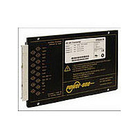
CP2101-9R POWER ONE, CP2101-9R Datasheet - Page 20

CP2101-9R
Manufacturer Part Number
CP2101-9R
Description
Manufacturer
POWER ONE
Type
Step Downr
Datasheet
1.CP2101-9R.pdf
(25 pages)
Specifications of CP2101-9R
Input Voltage
48V
Screening Level
Commercial
Operating Temperature Min Deg. C
-40C
Operating Temperature Max Deg. C
71C
Product Length (mm)
164mm
Product Depth (mm)
111mm
Product Height (mm)
19.8mm
Mounting Style
Din-Rail
Pin Count
15
Number Of Outputs
2
Lead Free Status / RoHS Status
Not Compliant
Safety and Installation Instructions
Connector Pin Allocation
The connector pin allocation table defines the electrical
potentials and the physical pin positions on the H15 and
H15S2 connector. Pin no. 26, protective earth, is a leading
pin to ensure that it makes contact with the female connector
first.
BCD20010-G Rev AC, 26-Aug-09
Table 13: Pin allocation
Notes:
• The current through each standard H15 contact depends on
• High currents require a large cross-sectional area of the
• For single-output models with option K, both output contacts
1
2
3
4
5
6
7
the female connector, the ambient temperature, and the air
flow in the region of the connector. We recommend to limit the
mean current to 15 A at 50 °C and to 13 A at 71 °C.
connections to the female contacts. We recommend solder or
screw terminal contacts. Each faston connection exhibits a
resistance of max. 8 m Ω, which makes it less suitable for high
currents.
must always be used and connected in parallel to the load with
large cross-sectional area wires or thick copper lands. The
efficiency is lower with option K.
Pin
10
Pin 4/6 (high-current contact) for P1000 models with 3.3 V or 5.1 V output (H15S2 connector, no option K)
Pin 8/10 (high-current contact) for P1000 models with 3.3 V or 5.1 V output (H15S2 connector, no option K)
Option T1 for 3.3 V and 5.1 V powertrains: Only I
Option D
Option i
Powertrains with 5.1 V and 3.3 V outputs have a common return: Vo1– and Vo4– are connected together.
Not connected, if option T is not fitted.
12
14
16
18
20
22
24
26
28
30
32
4
6
8
1
1
2
2
Vo+
Vo+
Vo–
Vo–
S+
S–
R
T
n.c.
n.c.
Out OK+
i+
n. c.
Out OK–
i–
i
Vi+
Vi–
7
P 1000
Output 1 pos.
Output 1 pos.
Output 1 neg.
Output 1 neg.
Sense +
Sense –
Adjust of V
Current share
Not connected
Not connected
Out OK+
Inhibit second.
Not connected
Out OK–
Inhibit second.
Prot. earth PE
Inhibit primary
Input pos.
Input neg.
®
4
4
o
5
5
Vo1+
Vo2+
Vo1–
Vo2–
S1+
S1–
R1
T1
S2+
S2–
n.c.
Out OK+
i+
n.c.
Out OK–
i–
i
Vi+
Vi–
o1
is influenced
P2000
Output 1 pos.
Output 2 pos.
Output 1 neg.
Output 2 neg.
Sense 1 +
Sense 1 –
Adjust of V
Current share
Sense 2 +
Sense 2 –
Not connected
Out OK+
Inhibit second.
Not connected
Out OK–
Inhibit second.
Prot. earth PE
Inhibit primary
Input pos.
Input neg.
Page 20 of 25
4
4
o1
3
5
5
Fig. 23a
View of male standard H15 connector
Fig. 23b
View of male H15S2 connector (with high-current contacts)
used in P1000 and P1100 without option K.
The H15-S2 connector is obsolete.
• High-current contacts of P1000 models exhibit no restriction of
the output current. Their resistance is only 1 m Ω.
Vo1+
Vo2+
Vo1–
Vo2–
S1+
S1–
R1
T1
Vo3+
Vo3–
n.c.
Out OK+
i+
n.c.
Out OK–
i–
i
Vi+
Vi–
90 – 194 Watt DC-DC Converters
32
32
30
30
Sense 1 +
Sense 1 –
Output 3 pos.
Output 3 neg.
28
P3000
Output 1 pos.
Output 2 pos.
Output 1 neg.
Output 2 neg.
Adjust of V
Current share
Not connected
Out OK+
Inhibit second.
Not connected
Out OK–
Inhibit second.
Prot. earth PE
Inhibit primary
Input pos.
Input neg.
28
26
26
24
24
22
22
4
4
20
20
o1
18
18
3
5
5
16
16
P Series Data Sheet
14
14
12
Vo1+
Vo2+
Vo1–
Vo2–
Vo4+
Vo4 –
R1
Vo3+
Vo3 –
n.c.
Out OK+
i+
n.c.
Out OK–
i–
i
Vi+
Vi–
12
10
8/10
8
6
4
www.power-one.com
4/6
Output 4 pos.
Output 4 neg.
P4000
Output 1 pos.
Output 2 pos.
Output 1 neg.
Output 2 neg.
Adjust of V
Output 3 pos.
Output 3 neg.
Out OK+
Inhibit second.
Out OK–
Inhibit second.
Prot. earth PE
Inhibit primary
Input pos.
Input neg.
Not connected
Not connected
10025a
S10051a
4
4
o1/4
6
6
5
5


