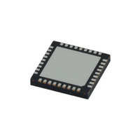
LMX2541SQE3320E/NOPB National Semiconductor, LMX2541SQE3320E/NOPB Datasheet - Page 2

LMX2541SQE3320E/NOPB
Manufacturer Part Number
LMX2541SQE3320E/NOPB
Description
IC PLL FREQ SYNTH W/VCO 36LLP
Manufacturer
National Semiconductor
Series
PowerWise®r
Type
Clock/Frequency Synthesizer (RF)r
Datasheet
1.LMX2541SQE2690ENOPB.pdf
(60 pages)
Specifications of LMX2541SQE3320E/NOPB
Pll
Yes
Input
Clock
Output
Clock
Number Of Circuits
1
Ratio - Input:output
2:2
Differential - Input:output
No/No
Frequency - Max
3.6GHz
Divider/multiplier
Yes/No
Voltage - Supply
3.15 V ~ 3.45 V
Operating Temperature
-40°C ~ 85°C
Mounting Type
Surface Mount
Package / Case
36-LLP
Frequency-max
3.6GHz
Lead Free Status / RoHS Status
Lead free / RoHS Compliant
Other names
LMX2541SQE3320ETR
Available stocks
Company
Part Number
Manufacturer
Quantity
Price
Company:
Part Number:
LMX2541SQE3320E/NOPB
Manufacturer:
NS
Quantity:
673
www.national.com
LMX2541 Frequency Coverage
All devices have continuous frequency coverage below a di-
vide value of 8 (7 for most devices) down to their minimum
frequency achievable with divide by 63. The numbers in bold
show the upper end of this minimum continuous frequency
range. For instance, the LMX2541SQ3740E option offers
Determining the Best Frequency Option of the LMX2541 to Use
When there are multiple devices that can satisfy the frequen-
cy requirement, performance characteristics can sometimes
be used to make a decision. Consider the following example
of where an output frequency of 1200 to 1250 MHz is desired
with a channel spacing of 100 kHz. From the frequency table,
Considering the fractional spurs and phase noise, the channel
spacing at the 2380E VCO would be 200 kHz. When this is
divided by two, the offset of these spurs does not change and
the spurs at the VCO output would be reduced by a factor of
20·log(2) = 6 dB. The channel spacing at the 3740E VCO
would be 300 kHz and these spurs would be reduced by a
factor of 20·log(3) = 9.5 dB. So the spurs of the 3740E option
would probably be better by virtue of the fact that they are
farther from the carrier and easier to filter and also that they
are divided down more by the VCO divider. The fractional
phase noise would also be (9.5 - 6) = 3.5 dB better by the
same reasoning.
Fractional Spurs
Characteristic
Fraction Noise
Performance
_DIV
VCO
VCO Phase
63
…
1
2
3
4
5
6
7
8
Noise
and
1990.0
995.0
663.3
497.5
398.0
331.7
284.3
248.8
Start
31.6
…
2060E
Larger Value
of VCO_DIV
Operating in
the
frequency
range of the
VCO
What Makes
it Better
2240.0
1120.0
746.7
560.0
448.0
373.3
320.0
280.0
Stop
35.6
…
lower
2200.0
1100.0
733.3
550.0
440.0
366.7
314.3
275.0
Start
34.9
…
Fractional spurs at the VCO are independent of VCO frequency, but when the VCO frequency
is divided down by a factor of VCO_DIV, the fractional spurs improve by a factor of 20·log
(VCO_DIV). Also, the fractional channel spacing can be made wider at the VCO, which makes
the fractional spurs farther from the carrier.
The fractional noise of the modulator is divided down in a similar way as fractional spurs. In
applications where this is dominant, this larger division can have an impact. Consult the
applications section for more information on the fractional phase noise.
At the lower end of the tuning range, the VCO phase noise is less because the tuning gain is
less. This provides better phase noise, even accounting for the difference in frequency.
2380E
2530.0
1265.0
843.3
632.5
506.0
421.7
361.4
316.3
Stop
40.2
…
2490.0
1245.0
830.0
622.5
498.0
415.0
355.7
311.3
Start
39.5
…
2690E
2865.0
1432.5
955.0
716.3
573.0
477.5
409.3
358.1
Stop
45.5
…
2
continuous frequency coverage from 55.2 MHz to 571.4 MHz
and LMX2541SQ2060E offers continuous frequency cover-
age from 31.6 MHz to 280 MHz. If using the part in External
VCO mode, all parts have roughly the same performance and
any option will do.
the LMX2541SQ2380E could be used with with a divide value
of 2, or the LMX2541SQ3740E option could be used with a
divide value of 3. This raises the question: Which one has
better performance? The following table is helpful in compar-
ing the performance.
Now consider the VCO phase noise. For the 3740E option,
1200 - 1250 MHz corresponds to a VCO frequency of 3600 -
3750 MHz, which is closer to the lower end of the tuning range
for this device. For the 2380E option, this would correspond
to 2400 - 2500 MHz, which is closer to the higher end of the
tuning range.. To verify this, take the phase noise numbers
from the electrical specifications, extrapolate them to the ac-
tual frequencies, and then subtract a factor of 20·log
(VCO_DIV). For the 2380E option, this works out to -116 dBc/
Hz at 1200 MHz and -115.4 dBc/Hz at 1250 MHz. For the
3740E option, this works out to -117.4 dBc/Hz at 1200 MHz
and -116.9 dBc/Hz at 1250 MHz.
2810.0
1405.0
936.7
702.5
562.0
468.3
401.4
351.3
Start
44.6
…
3030E
Why
3230.0
1615.0
1076.7
807.5
646.0
538.3
461.4
403.8
Stop
51.3
…
3130.0
1565.0
1043.3
782.5
626.0
521.7
447.1
391.3
Start
49.7
…
3320E
3600.0
1800.0
1200.0
900.0
720.0
600.0
514.3
450.0
Stop
57.1
…
3480.0
1740.0
1160.0
870.0
696.0
580.0
497.1
435.0
Start
55.2
…
3740E
4000.0
2000.0
1333.3
1000.0
800.0
666.7
571.4
500.0
Stop
63.5
…


