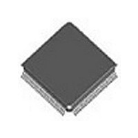
PEB20571FV3.1XT Infineon Technologies, PEB20571FV3.1XT Datasheet - Page 145

PEB20571FV3.1XT
Manufacturer Part Number
PEB20571FV3.1XT
Description
Manufacturer
Infineon Technologies
Datasheet
1.PEB20571FV3.1XT.pdf
(308 pages)
Specifications of PEB20571FV3.1XT
Lead Free Status / Rohs Status
Compliant
- Current page: 145 of 308
- Download datasheet (5Mb)
Note: The NMI interrupt maybe enabled/disabled in the INTMASK register.
4.8.4
The DSP run time statistics is used for the DSP work load estimation. By using this HW,
the maximum time spent by the DSP from the FSC until the tasks ends may be found.
The DSP statistics include an eight bit counter STATC which is counting up every 1 s.
Figure 51
STATC is reset upon FSC rising edge. When the DSP finishes a task, it reads STATC.
The time between two consecutive FSC is always 125 s, therefore, if the DSP is
working properly, the counter value should always be less then 125 s.
If the DSP failed to read the counter value and a new FSC rising edge has arrived, the
counter is not reset. Therefore, the DSP reads a value greater then 125. It means that
the DSP failed to finish it’s tasks within the time frame of 125 s.
The STATI register is added for helping the user to perform the statistics. STATI is a
general purpose 8-bit read/write register.
Data Sheet
1 s
Reset by FSC of the frame n+1, only if
the DSP has read the counter already
DSP Run Time Statistics
Statistics Registers
Counter (in Frame n)
STATC
DSP
128
Maximum Value Register
Functional Description
STATI
DSP
PEB 20570
PEB 20571
2003-07-31
Related parts for PEB20571FV3.1XT
Image
Part Number
Description
Manufacturer
Datasheet
Request
R

Part Number:
Description:
Manufacturer:
Infineon Technologies
Datasheet:

Part Number:
Description:
ICs for Communications
Manufacturer:
INFINEON [Infineon Technologies AG]
Datasheet:

Part Number:
Description:
Manufacturer:
Infineon Technologies AG
Datasheet:

Part Number:
Description:
Manufacturer:
Infineon Technologies AG
Datasheet:

Part Number:
Description:
Manufacturer:
Infineon Technologies AG
Datasheet:

Part Number:
Description:
Manufacturer:
Infineon Technologies AG
Datasheet:

Part Number:
Description:
Manufacturer:
Infineon Technologies AG
Datasheet:

Part Number:
Description:
Manufacturer:
Infineon Technologies AG
Datasheet:

Part Number:
Description:
Manufacturer:
Infineon Technologies AG
Datasheet:

Part Number:
Description:
16-bit microcontroller with 2x2 KByte RAM
Manufacturer:
Infineon Technologies AG
Datasheet:

Part Number:
Description:
NPN silicon RF transistor
Manufacturer:
Infineon Technologies AG
Datasheet:

Part Number:
Description:
NPN silicon RF transistor
Manufacturer:
Infineon Technologies AG
Datasheet:

Part Number:
Description:
NPN silicon RF transistor
Manufacturer:
Infineon Technologies AG
Datasheet:

Part Number:
Description:
NPN silicon RF transistor
Manufacturer:
Infineon Technologies AG
Datasheet:

Part Number:
Description:
Si-MMIC-amplifier in SIEGET 25-technologie
Manufacturer:
Infineon Technologies AG
Datasheet:


