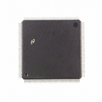
DP83950BVQB National Semiconductor, DP83950BVQB Datasheet - Page 39

DP83950BVQB
Manufacturer Part Number
DP83950BVQB
Description
IC CTRLR RIC REPEATER 160-PQFP
Manufacturer
National Semiconductor
Datasheet
1.DP83950BVQB.pdf
(80 pages)
Specifications of DP83950BVQB
Controller Type
Ethernet Repeater Interface Controller
Interface
IEEE 802.3
Voltage - Supply
4.75 V ~ 5.25 V
Current - Supply
380mA
Operating Temperature
0°C ~ 70°C
Mounting Type
Surface Mount
Package / Case
160-MQFP, 160-PQFP
Lead Free Status / RoHS Status
Contains lead / RoHS non-compliant
Other names
*DP83950BVQB
Available stocks
Company
Part Number
Manufacturer
Quantity
Price
Company:
Part Number:
DP83950BVQB
Manufacturer:
NS
Quantity:
43
Company:
Part Number:
DP83950BVQB
Manufacturer:
Texas Instruments
Quantity:
10 000
Signal Pin Name
5 0 Functional Description
5 6 DESCRIPTION OF HARDWARE
CONNECTION FOR PROCESSOR
AND DISPLAY INTERFACE
Display Update Cycles
The RIC possesses control logic and interface pins which
may be used to provide status information concerning activi-
ty on the attached network segments and the current status
of repeater functions These status cycles are completely
autonomous and require only simple support circuitry to pro-
duce the data in a form suitable for a light emitting diode
‘‘LED’’ display The display may be used in one of two
modes
1 Minimum Mode General Repeater Status LEDs
2 Maximum Mode Individual Port Status LEDs
Minimum mode intended for simple LED displays makes
available four status indicators The first LED denotes
whether the RIC has been forced to activate its jabber pro-
tect functions The remaining 3 LEDs indicate if any of the
RIC’s network segments are (1) experiencing a collision (2)
receiving data (3) currently partitioned When minimum dis-
play mode is selected the only external components re-
quired are a 74LS374 type latch the LEDs and their current
limiting resistors
Maximum mode differs from minimum mode by providing
display information specific to individual network segments
This information denotes the collision activity packet recep-
tion and partition status of each segment In the case of
10BASE-T segments the link integrity status and polarity of
the received data are also made available The wide variety
of information available in maximum mode may be used in
its entirety or in part Thus allowing the system designer to
choose the appropriate complexity of status display com-
mensurate with the specification of the end equipment
D(7 5)
STR0
STR1
D0
D1
D2
D3
D4
No operation
Provides status information indicating if there is a collision occurring on one of the segments attached to this
RIC
Provides status information indicating if one of this RIC’s ports is receiving a data or collision packet from a
segment attached to this RIC
Provides status information indicating that the RIC has experienced a jabber protect condition
Provides Status information indicating if one of the RIC’s segments is partitioned
No operation
This signal is the latch enable for the 374 type latch
This signal is held at a logic one
TABLE 5 2 Status Display Pin Functions in Minimum Mode
(Continued)
Function in MINIMUM MODE
39
The signals provided and their timing relationships have
been designed to interface directly with 74LS259 type ad-
dressable latches The number of latches used being de-
pendant upon the complexity of the display Since the latch-
es are octal a pair of latches is needed to display each type
of segment specific data (13 ports means 13 latch bits) The
accompanying tables (5 1 and 5 2) show the function of the
interface pins in minimum and maximum modes Figure 5 12
shows the location of each port’s status information when
maximum mode is selected This may be compared with the
connection diagram Figure 5 11
Immediately following the Mode Load Operation (when the
MLOAD pin transitions to a high logic state) the display
logic performs an LED test operation This operation lasts
one second and while it is in effect all of the utilized LEDs
will blink on Thus an installation engineer is able to test the
operation of the display by forcing the RIC into a reset cycle
(MLOAD forced low) The rising edge on the MLOAD pin
starts the LED test cycle During the LED test cycle the
RIC does not perform packet repetition operations
The status display possesses a capability to lengthen the
time an LED is active At the end of the repetition of a pack-
et the display is frozen showing the current activity This
freezing lasts for 30 milliseconds or until a subsequent
packet is repeated Thus at low levels of packet activity the
display stretches activity information to make it discernable
to the human eye At high traffic rates the relative bright-
ness of the LEDs indicates those segments with high or low
activity
It should be mentioned that when the Real Time Interrupt
(RTI) occurs the display update cycle will stop and after RTI
is serviced the display update cycle will resume activity


