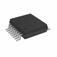
AD5933YRSZ Analog Devices Inc, AD5933YRSZ Datasheet - Page 33

AD5933YRSZ
Manufacturer Part Number
AD5933YRSZ
Description
IC NTWK ANALYZER 12B 1MSP 16SSOP
Manufacturer
Analog Devices Inc
Datasheet
1.AD5933YRSZ.pdf
(44 pages)
Specifications of AD5933YRSZ
Resolution (bits)
12 b
Master Fclk
16.776MHz
Voltage - Supply
2.7 V ~ 5.5 V
Operating Temperature
-40°C ~ 125°C
Mounting Type
Surface Mount
Package / Case
16-SSOP
Supply Voltage Range
2.7V To 5.5V
Operating Temperature Range
-40°C To +125°C
Digital Ic Case Style
SSOP
No. Of Pins
16
Frequency Max
0.1MHz
Termination Type
SMD
Pin Count
16
Screening Level
Automotive
Package Type
SSOP
Filter Terminals
SMD
Rohs Compliant
Yes
Communication Function
Network Analyzer
Lead Free Status / RoHS Status
Lead free / RoHS Compliant
For Use With
EVAL-AD5933EBZ - BOARD EVALUATION FOR AD5933
Tuning Word Width (bits)
-
Lead Free Status / Rohs Status
Compliant
Other names
AD5933BRSZ
Q2204656A
Q2204656A
Available stocks
Company
Part Number
Manufacturer
Quantity
Price
Company:
Part Number:
AD5933YRSZ
Manufacturer:
ADI
Quantity:
5 000
Company:
Part Number:
AD5933YRSZ
Manufacturer:
Fujitsu
Quantity:
500
Part Number:
AD5933YRSZ
Manufacturer:
ADI/亚德诺
Quantity:
20 000
BIOMEDICAL: NONINVASIVE BLOOD IMPEDANCE
MEASUREMENT
When a known strain of a virus is added to a blood sample
that already contains a virus, a chemical reaction takes place
whereby the impedance of the blood under certain conditions
changes. By characterizing this effect across different frequencies,
it is possible to detect a specific strain of virus. For example, a
strain of the disease exhibits a certain characteristic impedance
at one frequency but not at another; therefore, the requirement
is to sweep different frequencies to check for different viruses.
The AD5933, with its 27-bit phase accumulator, allows for
subhertz frequency tuning.
the blood sample via a probe. The response signal is analyzed,
and the effective impedance of the blood is tabulated. The
AD5933 is ideal for this application because it allows the user
to tune to the specific frequency required for each test.
The AD5933 can be used to inject a stimulus signal through
PROBE
Figure 42. Measuring a Blood Sample for a Strain of Virus
0.1µF
7V
10µF
RFB
1
2
3
4
5
6
7
8
2
(Not to Scale)
AD5933
TOP VIEW
ADR43x
4
16
15
14
13
12
11
10
9
6
(Not to Scale)
ADuC702x
TOP VIEW
Rev. C | Page 33 of 44
SENSOR/COMPLEX IMPEDANCE MEASUREMENT
The operational principle of a capacitive proximity sensor is
based on the change of a capacitance in an RLC resonant
circuit. This leads to changes in the resonant frequency of the
RLC circuit, which can be evaluated as shown Figure 43.
It is first required to tune the RLC circuit to the area of
resonance. At the resonant frequency, the impedance of the
RLC circuit is at a maximum. Therefore, a programmable
frequency sweep and tuning capability is required, which is
provided by the AD5933.
An example of the use of this type of sensor is for a train
proximity measurement system. The magnetic fields of the
train approaching on the track change the resonant frequency
to an extent that can be characterized. This information can be
sent back to a mainframe system to show the train location
on the network.
Another application for the AD5933 is in parked vehicle detec-
tion. The AD5933 is placed in an embedded unit connected to
a coil of wire underneath the parking location. The AD5933
outputs a single frequency within the 80 kHz to 100 kHz
frequency range, depending upon the wire composition. The
wire can be modeled as a resonant circuit. The coil is calibrated
with a known impedance value and at a known frequency. The
impedance of the loop is monitored constantly. If a car is parked
over the coil, the impedance of the coil changes and the
AD5933 detects the presence of the car.
Figure 43. Detecting a Change in Resonant Frequency
FREQUENCY
RESONANT
FREQUENCY (Hz)
F
O
TO APPROACHING
RESONANCE DUE
CHANGE IN
OBJECT
AD5933


