MIKROE-415 mikroElektronika, MIKROE-415 Datasheet - Page 13
MIKROE-415
Manufacturer Part Number
MIKROE-415
Description
Development Boards & Kits - AVR EASYAVR6 DEVELOPMENT SYSTEM
Manufacturer
mikroElektronika
Datasheet
1.MIKROE-415.pdf
(28 pages)
Specifications of MIKROE-415
Tool Type
AVR Development Board
Interface Type
RS-232, USB, JTAG UART
Dimensions
265 mm x 220 mm
Operating Supply Voltage
9 V to 32 V
Lead Free Status / Rohs Status
Details


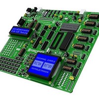
EasyAVR6 Development System
EasyAVR6 Development System
9.0. USB UART Module
When the USB UART module is used, it is possible to connect the microcontroller on the development system to the external USB
device. The USB UART module features the FT232RL circuit which serves as an interface between a USB device and the microcon-
troller’s serial UART module. In order to establish connection between the microcontroller and the USB UART module it is necessary
to place jumpers J16 and J17 as shown in Figure 9-2, thus connecting RX-MCU and TX-MCU pins of the circuit FT232RL to the
microcontroller pins PD0 and PD1.
When connecting the UART module to the microcontroller it is necessary to combine the transmit and receive lines, i.e. to connect
the UART module’s RX pin to the microcontroller pin TX and the UART module’s TX pin to the microcontroller pin RX. Otherwise, it
wouldn’t be possible to connect the UART module’s transmit line (TX) to the microcontroller transmit line (TX). It further means that
the microcontroller wouldn’t be able to receive and transmit data.
Figure 9-3: USB UART module and microcontroller connection schematic
Figure 9-1: USB UART
module (J16 and J17 are
not placed)
Jumpers J16 and J17 are placed
Figure 9-2: USB UART
module (J16 and J17 are
placed)
USB connector
MikroElektronika
13
Related parts for MIKROE-415
Image
Part Number
Description
Manufacturer
Datasheet
Request
R

Part Number:
Description:
Development Boards & Kits - PIC / DSPIC PIC-READY1 28-40 PIN PROTOTYPE BOARD
Manufacturer:
mikroElektronika
Datasheet:

Part Number:
Description:
Daughter Cards & OEM Boards SERIAL ETHERNET 2 ADAPTER BOARD
Manufacturer:
mikroElektronika
Datasheet:

Part Number:
Description:
Daughter Cards & OEM Boards RS485 (ADM485) ADAPTER BOARD
Manufacturer:
mikroElektronika

Part Number:
Description:
Daughter Cards & OEM Boards EASYCONNECT2 ADAPTER BOARD
Manufacturer:
mikroElektronika

Part Number:
Description:
Daughter Cards & OEM Boards SMARTPROTO PROTO ADAPTER BOARD
Manufacturer:
mikroElektronika

Part Number:
Description:
Daughter Cards & OEM Boards CAN SPI (MCP2551) TRANSCEIVER BOARD
Manufacturer:
mikroElektronika

Part Number:
Description:
Development Boards & Kits - PIC / DSPIC BIGPIC6 PROTO PROTOTYPE BOARD
Manufacturer:
mikroElektronika

Part Number:
Description:
Sockets & Adapters GLCD 240x128 SERIAL ADAPTER BOARD
Manufacturer:
mikroElektronika

Part Number:
Description:
Daughter Cards & OEM Boards ACCEL 3-AXIS ADAPTER BOARD
Manufacturer:
mikroElektronika

Part Number:
Description:
Daughter Cards & OEM Boards 3.3V VOLTAGE REGULATOR BOARD
Manufacturer:
mikroElektronika

Part Number:
Description:
Daughter Cards & OEM Boards USB UART 2 ADAPTER BOARD
Manufacturer:
mikroElektronika

Part Number:
Description:
Development Boards & Kits - PIC / DSPIC LV24-33 V6 DEVELOPMENT SYSTEM
Manufacturer:
mikroElektronika

Part Number:
Description:
Microcontroller Modules MCU CARD LV-32MX V6 100P PIC32MX460F512L
Manufacturer:
mikroElektronika

Part Number:
Description:
Microcontroller Modules MCU CARD BIGAVR6 100P W/ ATMEGA2560
Manufacturer:
mikroElektronika

Part Number:
Description:
Bluetooth / 802.15.1 Modules BLUETOOTH 2 STICK ADAPTER BOARD
Manufacturer:
mikroElektronika
Datasheet: