MIKROE-415 mikroElektronika, MIKROE-415 Datasheet - Page 22
MIKROE-415
Manufacturer Part Number
MIKROE-415
Description
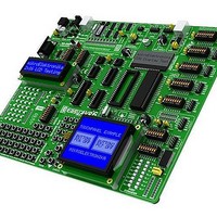
Development Boards & Kits - AVR EASYAVR6 DEVELOPMENT SYSTEM
Manufacturer
mikroElektronika
Datasheet
1.MIKROE-415.pdf
(28 pages)
Specifications of MIKROE-415
Tool Type
AVR Development Board
Interface Type
RS-232, USB, JTAG UART
Dimensions
265 mm x 220 mm
Operating Supply Voltage
9 V to 32 V
Lead Free Status / Rohs Status
Details


22
Figure 18-3: Placing touch panel
MikroElektronika
18.0.
18.0. Touch Panel
The touch panel is a thin, self-adhesive, transparent panel sensitive to touch. It is placed over a GLCD. The main purpose of this panel
is to register pressure at some specifi c display point and to forward its coordinates in the form of analog voltage to the microcontroller.
Switches 5,6,7 and 8 on the DIP switch SW8 are used for connecting touch panel to the microcontroller.
Figure 18-1: Touch panel
Figure 18-1 shows how to place a touch panel over a GLCD. Make sure that the fl at cable is to the left of the GLCD, as shown in
Figure 4.
Figure 18-2: Touch panel connection schematic
Figure 18-3 shows in detail how to connect a touch panel to the microcontroller. Bring the end of the fl at cable close to the CN13 connector as
shown in Figure 1. Plug the cable into the connector, as shown in Figure 2, and press it easily so as to fi t the connector, as shown in Figure
3. Now you can plug a GLCD into the appropriate connector as shown in Figure 4.
NOTE:
SW8: BOTTOM, LEFT, DRIVEA, DRIVEB = ON
1
1
CN13
RIGHT
TOP
LEFT
BOTTOM
Touch Panel
LEDs and pull-up/pull-down resistors on the PORTA port must be turned off when using a touch panel.
1
20
GLCD
RIGHT
TOP
LEFT
BOTTOM
VCC-MCU
VCC-MCU
Q14
BC856
Q
BC856
15
R52
100
R53
100
K
K
R49
1 K
R46
1 K
0
0
Q12
BC846
Q
BC846
16
TOUCHPANEL
CONTROLLER
Q
BC846
R48
1K
R45
1 K
R51
1 K
13
0
0
VCC-MCU
R47
1 K
VCC-MCU
0
3
R44
1K
R50
1K
3
BO TOM
DRIVEA
DRIVEB
T
LEFT
EasyAVR6 Development System
EasyAVR6 Development System
SW8
PA0
PA1
PA2
PA3
VCC
4
DIP40
PB0
PB1
PB2
PB3
PB4
PB5
PB6
PB7
RESET
VCC
GND
XTAL2
XTAL1
PD0
PD1
PD2
PD3
PD4
PD5
PD6
4
AVCC
AREF
GND
PC7
PC6
PC5
PC4
PC3
PC2
PC0
PD7
PA0
PA2
PA3
PA4
PA5
PA6
PA7
PC1
PA1
VCC
Related parts for MIKROE-415
Image
Part Number
Description
Manufacturer
Datasheet
Request
R

Part Number:
Description:
Development Boards & Kits - PIC / DSPIC PIC-READY1 28-40 PIN PROTOTYPE BOARD
Manufacturer:
mikroElektronika
Datasheet:

Part Number:
Description:
Daughter Cards & OEM Boards SERIAL ETHERNET 2 ADAPTER BOARD
Manufacturer:
mikroElektronika
Datasheet:

Part Number:
Description:
Daughter Cards & OEM Boards RS485 (ADM485) ADAPTER BOARD
Manufacturer:
mikroElektronika

Part Number:
Description:
Daughter Cards & OEM Boards EASYCONNECT2 ADAPTER BOARD
Manufacturer:
mikroElektronika

Part Number:
Description:
Daughter Cards & OEM Boards SMARTPROTO PROTO ADAPTER BOARD
Manufacturer:
mikroElektronika

Part Number:
Description:
Daughter Cards & OEM Boards CAN SPI (MCP2551) TRANSCEIVER BOARD
Manufacturer:
mikroElektronika

Part Number:
Description:
Development Boards & Kits - PIC / DSPIC BIGPIC6 PROTO PROTOTYPE BOARD
Manufacturer:
mikroElektronika

Part Number:
Description:
Sockets & Adapters GLCD 240x128 SERIAL ADAPTER BOARD
Manufacturer:
mikroElektronika

Part Number:
Description:
Daughter Cards & OEM Boards ACCEL 3-AXIS ADAPTER BOARD
Manufacturer:
mikroElektronika

Part Number:
Description:
Daughter Cards & OEM Boards 3.3V VOLTAGE REGULATOR BOARD
Manufacturer:
mikroElektronika

Part Number:
Description:
Daughter Cards & OEM Boards USB UART 2 ADAPTER BOARD
Manufacturer:
mikroElektronika

Part Number:
Description:
Development Boards & Kits - PIC / DSPIC LV24-33 V6 DEVELOPMENT SYSTEM
Manufacturer:
mikroElektronika

Part Number:
Description:
Microcontroller Modules MCU CARD LV-32MX V6 100P PIC32MX460F512L
Manufacturer:
mikroElektronika

Part Number:
Description:
Microcontroller Modules MCU CARD BIGAVR6 100P W/ ATMEGA2560
Manufacturer:
mikroElektronika

Part Number:
Description:
Bluetooth / 802.15.1 Modules BLUETOOTH 2 STICK ADAPTER BOARD
Manufacturer:
mikroElektronika
Datasheet: