MIKROE-415 mikroElektronika, MIKROE-415 Datasheet - Page 18

MIKROE-415
Manufacturer Part Number
MIKROE-415
Description
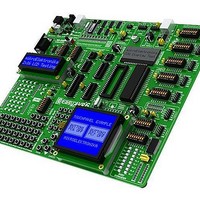
Development Boards & Kits - AVR EASYAVR6 DEVELOPMENT SYSTEM
Manufacturer
mikroElektronika
Datasheet
1.MIKROE-415.pdf
(28 pages)
Specifications of MIKROE-415
Tool Type
AVR Development Board
Interface Type
RS-232, USB, JTAG UART
Dimensions
265 mm x 220 mm
Operating Supply Voltage
9 V to 32 V
Lead Free Status / Rohs Status
Details
18
Figure 14-1: Keypad 4x4
MikroElektronika
14.0. Keypads
14.0. Keypads
There are two keypads provided on the EasyAVR6 development system. These are keypad 4x4 and keypad MENU. Keypad 4x4 is a
standard alphanumeric keypad connected to the microcontroller PORTC. The performance of such keypad is based on the ‘scan and
sense’ principle where the PC0, PC1, PC2 and PC3 pins are confi gured as inputs connected to pull-down resistors. The PC4, PC5,
PC6 and PC7 pins are confi gured as high level voltage outputs. Pressing any button will cause a logic one (1) to be applied to input
pins. Push button detection is performed from within software. For example, pressing button ‘6’ will cause a logic one (1) to appear
on the PC2 pin. In order to determine which of the push buttons is pressed, a logic one (1) is applied to each of the following output
pins PC4, PC5, PC6 and PC7.
Keypad MENU buttons are connected in a similar way to the PORTA buttons. The only difference is in the button arrangement. The
keypad MENU buttons are arranged so as to provide easy navigation through menus.
Figure 14-4: Keypads (4x4 and MENU) and microcontroller connection schematic
Jumper J13 is in
the VCC position.
Pins PC0, PC1,
PC2
are connected to
pull-down resis-
tors through DIP
switch SW3
and
PC3
Figure 14-2: Keypad 4x4 performance
PC7
PC6
PC5
PC4
PC3
PC2
PC1
PC0
"1"
"1"
"1"
"1"
Pull-down
EasyAVR6 Development System
EasyAVR6 Development System
Figure 14-3: Keypad MENU


