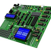
MIKROE-415 mikroElektronika, MIKROE-415 Datasheet - Page 16

MIKROE-415
Manufacturer Part Number
MIKROE-415
Description
Development Boards & Kits - AVR EASYAVR6 DEVELOPMENT SYSTEM
Manufacturer
mikroElektronika
Datasheet
1.MIKROE-415.pdf
(28 pages)
Specifications of MIKROE-415
Tool Type
AVR Development Board
Interface Type
RS-232, USB, JTAG UART
Dimensions
265 mm x 220 mm
Operating Supply Voltage
9 V to 32 V
Lead Free Status / Rohs Status
Details
16
Figure 12-1: LEDs
MikroElektronika
12.0.
12.0. LEDs
LED diode (Light-Emitting Diode) is a highly effi cient electronic light source. When connecting LEDs, it is necessary to place a current
limiting resistor, the value of which is calculated using formula R=U/I where R is referred to resistance expressed in ohms, U is referred to
voltage on the LED and I stands for LED diode current. A common LED diode voltage is approximately 2.5V, while the current varies from
1mA to 20mA depending on the type of LED diode. The EasyAVR6 development system uses LEDs with current I=1mA.
The EasyAVR6 has 35 LEDs which visually indicate the state of each microcontroller I/O pin. An active LED diode indicates that a logic
one (1) is present on the pin. In order to enable the pin state to be shown, it is necessary to select appropriate port PORTA/E, PORTB,
PORTC or PORTD using the DIP switch SW8.
Figure 12-2: LED diodes and PORTA connection schematic
SW8: PORTA = ON
LEDs
VCC
DIP40
PD2
PB0
PB1
PB2
PB3
PB4
PB5
PB6
PB7
RESET
VCC
GND
XTAL2
XTAL1
PD0
PD1
PD3
PD4
PD5
PD6
AREF
AVCC
GND
PC7
PC6
PC5
PC4
PC3
PC2
PC0
PD7
PA0
PA2
PA3
PA4
PA5
PA6
PA7
PC1
PA1
VCC
PA0
PA1
PA2
PA3
PA4
PA5
PA7
PA6
MCU
LD1
LD2
LD3
LD4
LD5
LD6
LD7
LD8
Notch indicating the SMD LED cathode
Microcontroller
SMD resistor limiting current fl ow through an LED
PA0
PA1
PA2
PA3
PA4
A
EasyAVR6 Development System
EasyAVR6 Development System
A
SMD LED
RN13
PORTA/E
8x4K7
I
K
K
SW8
472
R
R=U/I


