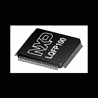
LPC2921_23_25 NXP Semiconductors, LPC2921_23_25 Datasheet - Page 24

LPC2921_23_25
Manufacturer Part Number
LPC2921_23_25
Description
The LPC2921/2923/2925 combine an ARM968E-S CPU core with two integrated TCMblocks operating at frequencies of up to 125 MHz, Full-speed USB 2
Manufacturer
NXP Semiconductors
Datasheet
1.LPC2921_23_25.pdf
(84 pages)
NXP Semiconductors
LPC2921_23_25_3
Product data sheet
6.12.2.1 Functional description
6.12.2.2 Clock description
6.12.3 Timer
The watchdog timer consists of a 32-bit counter with a 32-bit prescaler.
The watchdog should be programmed with a time-out value and then periodically
restarted. When the watchdog times out, it generates a reset through the RGU.
To generate watchdog interrupts in watchdog debug mode the interrupt has to be enabled
via the interrupt enable register. A watchdog-overflow interrupt can be cleared by writing
to the clear-interrupt register.
Another way to prevent resets during debug mode is via the Pause feature of the
watchdog timer. The watchdog is stalled when the ARM9 is in debug mode and the
PAUSE_ENABLE bit in the watchdog timer control register is set.
The Watchdog Reset output is fed to the Reset Generator Unit (RGU). The RGU contains
a reset source register to identify the reset source when the device has gone through a
reset. See
The watchdog timer is clocked by two different clocks; CLK_SYS_PESS and CLK_SAFE,
see
CLK_SYS_PESS. The timer and prescale counters are clocked by CLK_SAFE which is
always on.
The LPC2921/2923/2925 contains six identical timers: four in the peripheral subsystem
and two in the Modulation and Sampling Control SubSystem (MSCSS) located at different
peripheral base addresses. This section describes the four timers in the peripheral
subsystem. Each timer has four capture inputs and/or match outputs. Connection to
device pins depends on the configuration programmed into the port function-select
registers. The two timers located in the MSCSS have no external capture or match pins,
but the memory map is identical, see
input for a pause function.
The key features are:
•
•
•
•
•
•
Watchdog control register change-protected with key
Programmable 32-bit watchdog timer period with programmable 32-bit prescaler.
32-bit timer/counter with programmable 32-bit prescaler.
Up to four 32-bit capture channels per timer. These take a snapshot of the timer value
when an external signal connected to the TIMERx CAPn input changes state. A
capture event may also optionally generate an interrupt.
Four 32-bit match registers per timer that allow:
– Continuous operation with optional interrupt generation on match.
– Stop timer on match with optional interrupt generation.
– Reset timer on match with optional interrupt generation.
Up to four external outputs per timer corresponding to match registers, with the
following capabilities:
– Set LOW on match.
Section
Section
6.7.2. The register interface towards the system bus is clocked by
All information provided in this document is subject to legal disclaimers.
6.15.4.
Rev. 03 — 14 April 2010
Section
ARM9 microcontroller with CAN, LIN, and USB
6.14.6. One of these timers has an external
LPC2921/2923/2925
© NXP B.V. 2010. All rights reserved.
24 of 84


