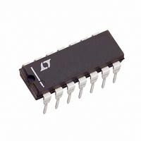
LT1105IN Linear Technology, LT1105IN Datasheet - Page 16

LT1105IN
Manufacturer Part Number
LT1105IN
Description
IC OFFLINE SWIT CM HV 14DIP
Manufacturer
Linear Technology
Datasheet
1.LT1105CN8PBF.pdf
(32 pages)
Specifications of LT1105IN
Output Isolation
Isolated
Frequency Range
20 ~ 200kHz
Voltage - Input
7 ~ 30 V
Voltage - Output
20V
Power (watts)
100W
Operating Temperature
-40°C ~ 125°C
Package / Case
14-DIP (0.300", 7.62mm)
Lead Free Status / RoHS Status
Contains lead / RoHS non-compliant
Available stocks
Company
Part Number
Manufacturer
Quantity
Price
Part Number:
LT1105IN
Manufacturer:
LINEAR/凌特
Quantity:
20 000
Part Number:
LT1105IN#PBF
Manufacturer:
LINEAR/凌特
Quantity:
20 000
Company:
Part Number:
LT1105IN8#PBF
Manufacturer:
LINEAR
Quantity:
29
Part Number:
LT1105IN8#PBF
Manufacturer:
LINEAR/凌特
Quantity:
20 000
LT1103/LT1105
APPLICATIONS
Bootstrap Start
It is inefficient as well as impractical to power a switching
regulator control IC from the rectified DC input as this
voltage is several hundred volts. Self-biased switching
regulator topologies take advantage of a lower voltage
auxiliary winding on the power transformer or inductor to
power the regulator, but require a start-up cycle to begin
regulation.
Start-up circuitry with hysteresis built into the LT1103/
LT1105 allows the input voltage to increase from 0V to
16V before the regulator tries to start. During this time the
start-up current of the switching regulator is typically
200 A and all internal voltage regulators are off. The low
quiescent current allows the input voltage to be trickled up
with only 500 A of current from the rectified DC line
voltage, thereby minimizing power dissipation in the start-
up resistor. At 16V, the internal voltage regulators are
turned on and switching begins. If enough power feeds
back through the auxiliary winding to keep the input
voltage to the switching regulator above 12V, then switching
continues and a bootstrap start is accomplished. If the
input voltage drops below 12V, then the FET drive detection
circuit locks out switching. The input voltage continues to
fall as the V
normal quiescent current of the LT1103/LT1105. Once the
input voltage falls below 7V, the internal voltage regulators
are turned off and the switching regulator returns to the
low start-up current state. A continuous “burp start” mode
indicates a fault condition or an incomplete power loop.
The trickle current required to bootstrap the regulator
input voltage is typically generated with a resistor from the
rectified DC input voltage. When combined with the
regulator input bypass capacitor, the start-up resistor
creates a ramp whose slope governs the turn-on time of
the regulator as well as the period of the “burp start” mode.
The design trade-offs are power dissipated in the trickle
resistor, the turn-on time of the regulator, and the hold-up
time of the regulator input bypass capacitor. The value of
the start-up resistor is set by the minimum rectified DC
input voltage to guarantee sufficient start-up current. The
recommended minimum trickle current is 500 A. The
power rating of the start-up resistor is set by the maximum
rectified DC input voltage. A final consideration for the
16
IN
bypass capacitor is discharged by the
U
INFORMATION
U
W
U
start-up resistor is to insure that the maximum voltage
rating of the resistor is not exceeded. Typical carbon film
resistors have a voltage rating of 250V. The most reliable
and economical solution for the start-up resistor is generally
provided by placing several 0.25W resistors in series.
The LT1103/LT1105 is designed to operate with supply
pin voltages up to 30V. However, the auxiliary bias winding
should be designed for a typical output voltage of 17V to
minimize IC power dissipation and efficiency loss.
Allowances must also be made for cross regulation of the
bias voltage due to variations in the rectified DC line
voltage and output load current.
Soft-Start
Soft-start refers to the controlled increase of switch
current from a start-up or shutdown state. This allows the
power supply to come up to voltage in a controlled
manner and charge the output capacitor without activating
current limit. In general, soft-start is not required on the
LT1105 due to the design of the sampling error amplifier
g
on the V
This feature exhibits itself as a typical 3mA sink current
capability on the V
275 A. The low g
valued compensation capacitors to be used on V
allows the sink current to slew the compensation capacitor
quickly. Therefore, overshoot of the output voltage on
start-up sequences and recovery from overload or short-
circuit conditions is prevented. However, if a longer start-
up period is required, the soft-start function can be used.
Soft-start is implemented with an internal 40 A pull-up
and a transistor clamp on the V
external capacitor from SS ground can define the linear
ramp function. The voltage at V
above the soft-start pin (SS). The time to maximum switch
current is defined as the capacitance on SS multiplied by
the active range in volts of the V
up current:
m
T
stage which generates asymmetrical slew capability
C • (3.2V)
C
40 A
pin.
m
C
of the error amplifier allows small-
pin whereas source current is only
C
C
pin divided by the pull-
C
is limited to one V
pin so that a single
C
. This
BE


