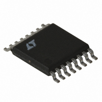
LT3433IFE Linear Technology, LT3433IFE Datasheet - Page 12

LT3433IFE
Manufacturer Part Number
LT3433IFE
Description
IC CONV DC/DC 200KHZ SW 16-TSSOP
Manufacturer
Linear Technology
Type
Step-Down (Buck), Step-Up (Boost)r
Datasheet
1.LT3433EFEPBF.pdf
(16 pages)
Specifications of LT3433IFE
Internal Switch(s)
Yes
Synchronous Rectifier
No
Number Of Outputs
1
Voltage - Output
3.3 ~ 20 V
Current - Output
500mA
Frequency - Switching
200kHz
Voltage - Input
4 ~ 60 V
Operating Temperature
-40°C ~ 125°C
Mounting Type
Surface Mount
Package / Case
16-TSSOP Exposed Pad, 16-eTSSOP, 16-HTSSOP
Lead Free Status / RoHS Status
Contains lead / RoHS non-compliant
Power - Output
-
Available stocks
Company
Part Number
Manufacturer
Quantity
Price
Part Number:
LT3433IFE
Manufacturer:
LINEAR/凌特
Quantity:
20 000
Company:
Part Number:
LT3433IFE#PBF
Manufacturer:
LT
Quantity:
5 000
Part Number:
LT3433IFE#PBF
Manufacturer:
LINEAR/凌特
Quantity:
20 000
Part Number:
LT3433IFE#TRPBF
Manufacturer:
LT凌特厂
Quantity:
20 000
LT3433
APPLICATIO S I FOR ATIO
Design Example
4V-60V to 5V DC/DC converter (the application on the
front page of this data sheet), load capability for T
The LT3433 operates in bridged mode with V
relations used are:
Iteration procedure for DC:
(1) Set initial seed value for I (this example will set
(2) Using seed value for I, determine I
(3) Use calculated I
(4) Use calculated DC to solve the I relation (yields I =
(5) If calculated I is equal to the seed value, stop.
12
Application Specific
Constants:
V
V
L = 100 H
R
V
V
R
DC = [V
I
V
I
SW
OUT(MAX)
0 = 0.55).
solve the DC relation (DC = 0.683).
0.0949).
Otherwise, use calculated I as new seed value and
repeat (2) through (4).
IN
OUT
F1
F2
F2
L
CESR
I = (V
I = 0).
= 0.28
]
= 4V
= 0.45V
= 0.4V
• (R
= 5V
= 0.01
OUT
OUT
SWH
= I
+ V
+ V
+ R
SW
F1
F1
SWL
• [1 – DC • (1 +
U
+ V
+ V
SW
F2
+ 2R
F2
and above design constants to
- I
U
– I
SW
L
SW
+ R
LT3433 W/C Constants:
I
R
R
f
I
I
MAX
O
VIN
BIAS
• R
SWH
SWL
BST
OUT
• (R
= 190kHz
ESR
L
= 600 A
W
) • (1 – DC)/(L • f
= 0.55A
= 800 A
= 0.05
= 0.05
L
= 1
) + V
BST
= 1.2
+ R
SW
+
ESR
OUT
IN
(I
OUT
)]/[V
SW
+ V
= 4V, so the
U
)] – I
A
= 0.55 –
F1
= 85 C.
IN
+
–
BIAS
O
)
After iteration, DC = 0.674 and I = 0.098.
Use iteration result for DC and above design constants to
solve the I
Increased Output Voltages
The LT3433 can be used in converter applications with
output voltages from 3.3V through 20V, but as converter
output voltages increase, output current and duty cycle
limitations prevent operation with V
end of the LT3433 operational range. When a converter
operates as a buck/boost, the output current becomes
discontinuous, which reduces output current capability by
roughly a factor of 1 – DC, where DC = duty cycle. As such,
the output current requirement dictates a minimum input
voltage where output regulation can be maintained.
ITERATION #
I
800 A
I
OUT(MAX)
OUT(MAX)
1
2
3
Typical Minimum Input Voltage as a Function of
Output Voltage and Required Load Current
OUT(MAX)
24
20
16
12
8
4
4
= 0.501 • [1 – 0.674 • (1 + 0.05 + 0.05)] –
= 129mA
SEED I
0.095
0.098
0
relation:
8
175mA
V
OUT
12
0.503
0.501
0.55
I
200mA
SW
(V)
CALCULATED VALUES
150mA
16
IN
125mA
at the extreme low
0.683
0.674
0.674
3433 AI03
DC
20
0.095
0.098
0.098
I
3433f


