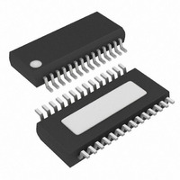
MAX1715EEI Maxim Integrated Products, MAX1715EEI Datasheet - Page 9

MAX1715EEI
Manufacturer Part Number
MAX1715EEI
Description
IC CTRLR DC DUAL STPDWN 28-QSOP
Manufacturer
Maxim Integrated Products
Type
Step-Down (Buck)r
Datasheet
1.MAX1715EEI.pdf
(25 pages)
Specifications of MAX1715EEI
Internal Switch(s)
No
Synchronous Rectifier
Yes
Number Of Outputs
2
Voltage - Output
1V, 1.8V, 2.5V, 3.3V, Adj
Current - Output
8A
Frequency - Switching
200kHz, 300kHz, 420kHz, 540kHz
Voltage - Input
2 ~ 28 V
Operating Temperature
-40°C ~ 85°C
Mounting Type
Surface Mount
Package / Case
28-QSOP
Power - Output
640mW
Output Voltage
1 V to 5.5 V, 3.3 V, 2.5 V
Output Current
8 A
Input Voltage
2 V to 28 V
Mounting Style
SMD/SMT
Maximum Operating Temperature
+ 85 C
Minimum Operating Temperature
- 40 C
Case
SSOP
Dc
05+
Lead Free Status / RoHS Status
Contains lead / RoHS non-compliant
Available stocks
Company
Part Number
Manufacturer
Quantity
Price
Part Number:
MAX1715EEI
Manufacturer:
MAXIM/美信
Quantity:
20 000
Company:
Part Number:
MAX1715EEI+
Manufacturer:
MAXIM
Quantity:
583
Part Number:
MAX1715EEI+
Manufacturer:
MAXIM/美信
Quantity:
20 000
Company:
Part Number:
MAX1715EEI+T
Manufacturer:
MAX
Quantity:
7 400
Part Number:
MAX1715EEI+T
Manufacturer:
MAXIM/美信
Quantity:
20 000
Part Number:
MAX1715EEI-T
Manufacturer:
MAXIM/美信
Quantity:
20 000
Company:
Part Number:
MAX1715EEI-TG069
Manufacturer:
MAXIN
Quantity:
2 268
Part Number:
MAX1715EEI-TG069
Manufacturer:
MAXOM
Quantity:
20 000
PIN
16
17
18
19
20
21
22
24
25
26
27
NAME
PGND
BST2
BST1
DH2
DH1
DL2
V
V
DL1
LX2
LX1
DD
CC
_______________________________________________________________________________________
External Inductor Connection for OUT2. Connect to the switched side of the inductor. LX2 serves as the
lower supply voltage rail for the DH2 high-side gate driver and is the positive input to the OUT2 current-limit
comparator.
High-Side Gate Driver Output for OUT2. Swings from LX2 to BST2.
Boost Flying Capacitor Connection for OUT2. Connect to an external capacitor and diode according to the
Standard Application Circuit (Figure 1). See MOSFET Gate Drivers (DH_, DL_) section.
Low-Side Gate-Driver Output for OUT2. DL2 swings from PGND to V
Supply Input for the DL Gate Drivers. Connect to the system supply voltage, +4.5V to +5.5V. Bypass to
PGND with a minimum 4.7µF ceramic capacitor.
Analog-Supply Input. Connect to the system supply voltage, +4.5V to +5.5V, with a 20Ω series resistor.
Bypass to AGND with a 1µF ceramic capacitor.
Power Ground. Connect directly to the low-side MOSFETs’ sources. Serves as the negative input of the cur-
rent-sense amplifiers.
Low-Side Gate Driver Output for OUT1. DL1 swings PGND to V
Boost Flying Capacitor Connection for OUT1. Connect to an external capacitor and diode according to the
Standard Application Circuit (Figure 1). See MOSFET Gate Drivers (DH_, DL_) section.
High-Side Gate Driver Output for OUT1. Swings from LX1 to BST1.
External Inductor Connection for OUT1. Connect to the switched side of the inductor. LX1 serves as the
lower supply voltage rail for the DH1 high-side gate driver.
Ultra-High Efficiency, Dual Step-Down
Controller for Notebook Computers
FUNCTION
Pin Description (continued)
DD
.
DD
.
9


