H5CX-L8-N AC100-240 Omron, H5CX-L8-N AC100-240 Datasheet - Page 19
H5CX-L8-N AC100-240
Manufacturer Part Number
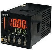
H5CX-L8-N AC100-240
Description
RELAY TIMER DGTL SPDT 100/240VAC
Manufacturer
Omron
Series
H5CXr
Specifications of H5CX-L8-N AC100-240
Relay Type
Integrated
Function
Programmable (Multi-Function)
Circuit
SPDT (1 Form C)
Delay Time
0.001 Sec ~ 9999 Hrs
Output Type
Mechanical Relay
Contact Rating @ Voltage
5A @ 250VAC
Voltage - Supply
100 ~ 240VAC
Mounting Type
Socket
Termination Style
8 Pin Socketable
Timing Adjustment Method
Up/Down Digit Keys
Timing Initiate Method
Input Voltage, Trigger Signal
Time Range
0.001s-9999hr
Power Consumption
6.2VA
Reset Time
20ms
Character Size
11.5mm
Time Range Min
0.001s
Supply Voltage Min
100VAC
Connector Type
8-Pin Socket
Signal Input Type
PNP/NPN
No. Of Digits / Alpha
4
Rohs Compliant
Yes
Lead Free Status / RoHS Status
Lead free / RoHS Compliant
For Use With
PNP/NPN
Lead Free Status / RoHS Status
Lead free / RoHS Compliant, Lead free / RoHS Compliant
Other names
H5CXL8NAC100240
Z2999
Z2999


Operation in Run Mode
Operating Procedures for Timer Function
Present Value and Set Value
These items are displayed when the power is turned ON. The present
value is displayed in the main display and the set value is displayed
in the sub-display.
The values displayed will be determined by the settings made for the
time range and the timer mode in function setting mode.
Present Value and ON Duty Ratio (Output Mode = Z)
The present value is displayed in the main display and the ON duty
ratio is displayed in the sub-display. Set the ON duty ratio used in ON/
OFF-duty-adjustable flicker mode (Z) as a percentage.
The output accuracy will vary with the time range, even if the ON duty
ratio setting is the same. Therefore, if fine output time adjustment is
required, it is recommended that the time range for the cycle time is
set as small as possible.
Examples: 1. When Time Range = - - - - s (9999 s)
If a cycle time is set, cyclic control can be performed in ON/OFF-duty-
adjustable flicker mode simply by changing the ON duty ratio.
Present Value and Cycle Time (Output Mode = Z)
The present value is displayed in the main display and the cycle time
is displayed in the sub-display. Set the cycle time.
ON time = Cycle time x
When Output Mode Z Is Selected
2. When Time Range = - -. - - s (99.99 s)
20.00(s) x
Rounded off to the nearest integer (because of the
time range setting) → ON time = 6 s
Rounded off to 2 decimal places (because of the time
range setting) → ON time = 6.20 s
20(s) x
31(%)
100
31(%)
100
ON duty ratio (%)
= 6.2(s)
100
= 6.200(s)
Present value
Set value
Present value
ON duty ratio
Present value
Cycle time
Set each digit for the output time using the corresponding
Note: H5CX-L8E@-N Precautions
Set each digit for the output time using the corresponding
(The
Set each digit for the output time using the corresponding
Set the Timer’s set value before using the Timer in a self-holding circuit.
keys for the 4th digit cannot be used.)
Control output
ON duty (%)
Cycle time
Elapsed cycle time
ON duty set as a percentage
Up/Down keys used for analog
adjustment of the ON duty
H5CX-A@-N/-L@-N
keys.
keys.
keys.
closing valve
Opening/
Close
ON duty
Open
Fully closed↔
Timer
0%↔100%
Fully open
19
Related parts for H5CX-L8-N AC100-240
Image
Part Number
Description
Manufacturer
Datasheet
Request
R

Part Number:
Description:
RELAY TIMER DIGITAL SPDT 100/240
Manufacturer:
Omron
Datasheet:

Part Number:
Description:
G6S-2GLow Signal Relay
Manufacturer:
Omron Corporation
Datasheet:
Part Number:
Description:
Compact, Low-cost, SSR Switching 5 to 20 A
Manufacturer:
Omron Corporation
Datasheet:
Part Number:
Description:
Manufacturer:
Omron Corporation
Datasheet:
Part Number:
Description:
Manufacturer:
Omron Corporation
Datasheet:
Part Number:
Description:
Manufacturer:
Omron Corporation
Datasheet:
Part Number:
Description:
Manufacturer:
Omron Corporation
Datasheet:
Part Number:
Description:
Manufacturer:
Omron Corporation
Datasheet:
Part Number:
Description:
Manufacturer:
Omron Corporation
Datasheet: