H5CX-L8-N AC100-240 Omron, H5CX-L8-N AC100-240 Datasheet - Page 22
H5CX-L8-N AC100-240
Manufacturer Part Number
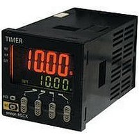
H5CX-L8-N AC100-240
Description
RELAY TIMER DGTL SPDT 100/240VAC
Manufacturer
Omron
Series
H5CXr
Specifications of H5CX-L8-N AC100-240
Relay Type
Integrated
Function
Programmable (Multi-Function)
Circuit
SPDT (1 Form C)
Delay Time
0.001 Sec ~ 9999 Hrs
Output Type
Mechanical Relay
Contact Rating @ Voltage
5A @ 250VAC
Voltage - Supply
100 ~ 240VAC
Mounting Type
Socket
Termination Style
8 Pin Socketable
Timing Adjustment Method
Up/Down Digit Keys
Timing Initiate Method
Input Voltage, Trigger Signal
Time Range
0.001s-9999hr
Power Consumption
6.2VA
Reset Time
20ms
Character Size
11.5mm
Time Range Min
0.001s
Supply Voltage Min
100VAC
Connector Type
8-Pin Socket
Signal Input Type
PNP/NPN
No. Of Digits / Alpha
4
Rohs Compliant
Yes
Lead Free Status / RoHS Status
Lead free / RoHS Compliant
For Use With
PNP/NPN
Lead Free Status / RoHS Status
Lead free / RoHS Compliant, Lead free / RoHS Compliant
Other names
H5CXL8NAC100240
Z2999
Z2999


22
H5CX-A@-N/-L@-N
Timer
* Start signal input is enabled during timing.
The control output is ON when the start signal is ON
(except when the power is OFF or the reset is ON).
The timer resets when the time is up.
Note: Output functions only during start signal input
* Start signal input is enabled during timing.
Timing starts when the start signal comes ON.
The timer resets when the time is up.
While the start signal is ON, the timer starts when the
power comes ON or when the reset input goes OFF.
Note: Output is disabled when the setting is 0.
Start signal enables timing (timing is stopped when the
start signal is OFF or when the power is OFF).
A sustained control output is used.
Note: Output is instantaneous when setting is 0.
When the H5CX is used with power start in mode F
mode or F-1 (i.e., cumulative operation with output on
hold), there will be a timer error (approximately 100 ms
each time the H5CX is turned ON) due to the
characteristics of the internal circuitry. Use the H5CX
with signal start if timer accuracy is required.
* Start signal input is disabled during timing.
Timing starts when the start signal goes ON.
The status of the control output is reversed when time is
up (ON at start).
While the start signal is ON, the timer starts when power
comes ON or when the reset input goes OFF.
Note: Normal output operation will not be possible if
Mode d: Signal OFF delay (Timer resets when power comes ON.)
Basic operation
Mode E: Interval (Timer resets when power comes ON.)
Basic operation
Mode F: Cumulative (Timer does not reset when power comes ON.)
Basic operation
Mode Z: ON/OFF-duty-adjustable flicker (Timer resets when power comes ON.)
Basic operation
Start signal
Start signal
Start signal
Start signal
Output
Output
Output
Power
Power
Power
Output
Power
input
input
input
when setting is 0.
the set time is too short.
Set the value to at least 100 ms (contact output
type).
input
*
*
*
ON duty
Timing
Timing
(cycle time)
(%)
Timing
Timing
Sustained
Timing
Timing
ON duty
Timing
(cycle time)
(%)
Timing
Detailed operation
Detailed operation
Detailed operation
Detailed operation
Control output
Control output
Control output
Start signal
Start signal
UP
DOWN
UP
DOWN
ON duty setting
ON duty setting
UP
DOWN
Set value
Set value
Set value
Set value
Start signal
Cycle time
(%) ON time
Cycle time
(%) ON time
Power
Power
Reset
Reset
Gate
Gate
Power
Reset
Gate
0
0
0
0
Control output
0
0
Start signal
UP
DOWN
Set value
Set value
Power
Reset
Gate
0
0
Related parts for H5CX-L8-N AC100-240
Image
Part Number
Description
Manufacturer
Datasheet
Request
R

Part Number:
Description:
RELAY TIMER DIGITAL SPDT 100/240
Manufacturer:
Omron
Datasheet:

Part Number:
Description:
G6S-2GLow Signal Relay
Manufacturer:
Omron Corporation
Datasheet:
Part Number:
Description:
Compact, Low-cost, SSR Switching 5 to 20 A
Manufacturer:
Omron Corporation
Datasheet:
Part Number:
Description:
Manufacturer:
Omron Corporation
Datasheet:
Part Number:
Description:
Manufacturer:
Omron Corporation
Datasheet:
Part Number:
Description:
Manufacturer:
Omron Corporation
Datasheet:
Part Number:
Description:
Manufacturer:
Omron Corporation
Datasheet:
Part Number:
Description:
Manufacturer:
Omron Corporation
Datasheet:
Part Number:
Description:
Manufacturer:
Omron Corporation
Datasheet: