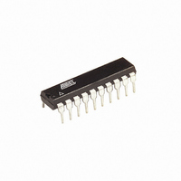
AT89LP2052-20PU Atmel, AT89LP2052-20PU Datasheet - Page 14

AT89LP2052-20PU
Manufacturer Part Number
AT89LP2052-20PU
Description
IC 8051 MCU FLASH 2K 20DIP
Manufacturer
Atmel
Series
89LPr
Datasheet
1.AT89LP2052-20PU.pdf
(94 pages)
Specifications of AT89LP2052-20PU
Core Processor
8051
Core Size
8-Bit
Speed
20MHz
Connectivity
SPI, UART/USART
Peripherals
Brown-out Detect/Reset, POR, PWM, WDT
Number Of I /o
15
Program Memory Size
2KB (2K x 8)
Program Memory Type
FLASH
Ram Size
256 x 8
Voltage - Supply (vcc/vdd)
2.4 V ~ 5.5 V
Oscillator Type
Internal
Operating Temperature
-40°C ~ 85°C
Package / Case
20-DIP (0.300", 7.62mm)
Processor Series
AT89x
Core
8051
Data Bus Width
8 bit
Data Ram Size
256 B
Interface Type
SPI/UART
Maximum Clock Frequency
20 MHz
Number Of Programmable I/os
15
Number Of Timers
2
Operating Supply Voltage
2.4 V to 5.5 V
Maximum Operating Temperature
+ 85 C
Mounting Style
Through Hole
3rd Party Development Tools
PK51, CA51, A51, ULINK2
Development Tools By Supplier
AT89ISP
Minimum Operating Temperature
- 40 C
Package
20PDIP
Device Core
8051
Family Name
AT89
Maximum Speed
20 MHz
Cpu Family
AT89
Device Core Size
8b
Frequency (max)
20MHz
Total Internal Ram Size
256Byte
# I/os (max)
15
Number Of Timers - General Purpose
2
Operating Supply Voltage (typ)
2.5/3.3/5V
Operating Supply Voltage (max)
5.5V
Operating Supply Voltage (min)
2.4V
Instruction Set Architecture
CISC
Operating Temp Range
-40C to 85C
Operating Temperature Classification
Industrial
Mounting
Through Hole
Pin Count
20
Package Type
PDIP
Lead Free Status / RoHS Status
Lead free / RoHS Compliant
Eeprom Size
-
Data Converters
-
Lead Free Status / Rohs Status
Lead free / RoHS Compliant
Available stocks
Company
Part Number
Manufacturer
Quantity
Price
Company:
Part Number:
AT89LP2052-20PU
Manufacturer:
ON
Quantity:
340
12. Reset
12.1
12.2
12.3
12.4
13. Power Saving Modes
14
Power-on Reset
Brown-out Reset
External Reset
Watchdog Reset
AT89LP2052/LP4052
During reset, all I/O Registers are set to their initial values, the port pins are tri-stated, and the
program starts execution from the Reset Vector, 0000H. The AT89LP2052/LP4052 has four
sources of reset: power-on reset, brown-out reset, external reset, and watchdog reset.
A Power-on Reset (POR) is generated by an on-chip detection circuit. The detection level is
nominally 1.4V. The POR is activated whenever V
cuit can be used to trigger the start-up reset or to detect a supply voltage failure in devices
without a brown-out detector. The POR circuit ensures that the device is reset from power-on.
When V
how long the device is kept in POR after V
any delay, when V
will set the POF flag in PCON.
The AT89LP2052/LP4052 has an on-chip Brown-out Detection (BOD) circuit for monitoring the
V
nominally 2.2V. The purpose of the BOD is to ensure that if V
speed, the system will gracefully enter reset without the possibility of errors induced by incorrect
execution. When V
diately activated. When V
MCU after the time-out period has expired.
The RST pin functions as an active-high reset input. The pin must be held high for at least two
clock cycles to trigger the internal reset. RST also serves as the In-System Programming (ISP)
enable. ISP is enabled when the external reset pin is held high and the ISP Enable fuse is
enabled.
When the Watchdog times out, it will generate an internal reset pulse lasting 16 clock cycles.
Watchdog reset will also set the WDTOVF flag in WDTCON. To prevent a Watchdog reset, the
watchdog reset sequence 1EH/E1H must be written to WDTRST before the Watchdog times
out. A Watchdog reset will occur only if the Watchdog has been enabled. The Watchdog is dis-
abled by default after any reset and must always be re-enabled if needed.
The AT89LP2052/LP4052 supports two different power-reducing modes: Idle and Power-down.
These modes are accessed through the PCON register.
CC
level during operation by comparing it to a fixed trigger level. The trigger level for the BOD is
CC
reaches the Power-on Reset threshold voltage, the POR delay counter determines
CC
CC
decreases to a value below the trigger level, the Brown-out Reset is imme-
falls below the POR threshold level. A Power-on Reset (i.e. a cold reset)
CC
increases above the trigger level, the BOD delay counter starts the
CC
rise. The POR signal is activated again, without
CC
is below the detection level. The POR cir-
CC
fails or dips while executing at
3547J–MICRO–10/09


