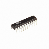
AT89LP2052-20PU Atmel, AT89LP2052-20PU Datasheet - Page 73

AT89LP2052-20PU
Manufacturer Part Number
AT89LP2052-20PU
Description
IC 8051 MCU FLASH 2K 20DIP
Manufacturer
Atmel
Series
89LPr
Datasheet
1.AT89LP2052-20PU.pdf
(94 pages)
Specifications of AT89LP2052-20PU
Core Processor
8051
Core Size
8-Bit
Speed
20MHz
Connectivity
SPI, UART/USART
Peripherals
Brown-out Detect/Reset, POR, PWM, WDT
Number Of I /o
15
Program Memory Size
2KB (2K x 8)
Program Memory Type
FLASH
Ram Size
256 x 8
Voltage - Supply (vcc/vdd)
2.4 V ~ 5.5 V
Oscillator Type
Internal
Operating Temperature
-40°C ~ 85°C
Package / Case
20-DIP (0.300", 7.62mm)
Processor Series
AT89x
Core
8051
Data Bus Width
8 bit
Data Ram Size
256 B
Interface Type
SPI/UART
Maximum Clock Frequency
20 MHz
Number Of Programmable I/os
15
Number Of Timers
2
Operating Supply Voltage
2.4 V to 5.5 V
Maximum Operating Temperature
+ 85 C
Mounting Style
Through Hole
3rd Party Development Tools
PK51, CA51, A51, ULINK2
Development Tools By Supplier
AT89ISP
Minimum Operating Temperature
- 40 C
Package
20PDIP
Device Core
8051
Family Name
AT89
Maximum Speed
20 MHz
Cpu Family
AT89
Device Core Size
8b
Frequency (max)
20MHz
Total Internal Ram Size
256Byte
# I/os (max)
15
Number Of Timers - General Purpose
2
Operating Supply Voltage (typ)
2.5/3.3/5V
Operating Supply Voltage (max)
5.5V
Operating Supply Voltage (min)
2.4V
Instruction Set Architecture
CISC
Operating Temp Range
-40C to 85C
Operating Temperature Classification
Industrial
Mounting
Through Hole
Pin Count
20
Package Type
PDIP
Lead Free Status / RoHS Status
Lead free / RoHS Compliant
Eeprom Size
-
Data Converters
-
Lead Free Status / Rohs Status
Lead free / RoHS Compliant
Available stocks
Company
Part Number
Manufacturer
Quantity
Price
Company:
Part Number:
AT89LP2052-20PU
Manufacturer:
ON
Quantity:
340
23.5
3547J–MICRO–10/09
In-System Programming (ISP)
Table 23-3.
The AT89LP2052/LP4052 offers a serial programming interface which may be used in place of
the parallel programming interface or to program the device while in system. In this document
serial programming and In-System Programming (ISP) refer to the same interface. ISP supports
the same command set as parallel programming. However, during ISP command bytes are
entered serially over the Serial Peripheral Interface (SPI) pins. The device connections are
shown in
ming prior to entering the first ISP session. ISP itself may disable the ISP Fuse, however any
changes to the ISP fuses will not take affect until the device has been powered down and up
again. The programmer must take care not to accidentally disable the ISP Fuse as this will make
the device unprogrammable through the serial interface. Only Parallel Programming may re-
enable the fuse.
V
V
I
t
t
t
t
t
t
t
t
t
t
t
t
t
t
t
t
t
t
t
t
PP
PWRUP
POR
CSTP
HSTL
CLXH
XTH
XTL
DSTP
DHLD
XLDO
XLDV
XLCH
CHDZ
CHBL
WRC
ERS
BHPG
BHHl
CLRL
PWRDN
Symbol
PPH
PPL
Figure
Parameter
Programming Enable Input High Voltage
Programming Enable Input Low Voltage
Programming Enable Current
Power-on to RST High
Power-on Reset Time
CS Setup to V
High Voltage Setting time
CS Low to XTAL1 High
XTAL1 High Width
XTAL1 Low Width
Data Setup to XTAL1 High
Data Hold after XTAL1 High
XTAL1 Low to Data Out
XTAL1 Low to Data Valid
XTAL1 Low to CS High
CS High to Data Tri-state
CS High to BUSY Low
Write Cycle Time
Erase Cycle Time
BUSY High to Next Erase/Write
BUSY High to V
CS Low to RST Low
RST Low to Power Off
Parallel Flash Programming and Verification Parameters
23-21. The ISP Enable User Fuse must be enabled through Parallel Program-
PP
PP
High
Off
AT89LP2052/LP4052
11.5
Min
-0.5
100
125
100
100
10
10
10
75
50
50
20
10
2
3
1
1
Max
12.5
V
1.0
4.5
20
3
9
CC
Units
mA
ms
ms
ms
µs
µs
µs
ns
ns
ns
ns
ns
ns
ns
ns
ns
µs
µs
µs
µs
µs
V
V
73


