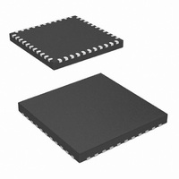
PIC18F47J13-I/ML Microchip Technology, PIC18F47J13-I/ML Datasheet - Page 401

PIC18F47J13-I/ML
Manufacturer Part Number
PIC18F47J13-I/ML
Description
IC PIC MCU 128KB FLASH 44QFN
Manufacturer
Microchip Technology
Series
PIC® XLP™ 18Fr
Datasheets
1.PIC18LF24J10-ISS.pdf
(32 pages)
2.PIC18F26J13-ISS.pdf
(496 pages)
3.PIC18F26J13-ISS.pdf
(558 pages)
4.PIC18F26J13-ISS.pdf
(12 pages)
Specifications of PIC18F47J13-I/ML
Core Size
8-Bit
Program Memory Size
128KB (64K x 16)
Core Processor
PIC
Speed
48MHz
Connectivity
I²C, LIN, SPI, UART/USART
Peripherals
Brown-out Detect/Reset, POR, PWM, WDT
Number Of I /o
34
Program Memory Type
FLASH
Ram Size
3.8K x 8
Voltage - Supply (vcc/vdd)
2.15 V ~ 3.6 V
Data Converters
A/D 13x10b/12b
Oscillator Type
Internal
Operating Temperature
-40°C ~ 85°C
Package / Case
*
Controller Family/series
PIC18
Cpu Speed
48MHz
Digital Ic Case Style
QFN
Supply Voltage Range
1.8V To 5.5V
Embedded Interface Type
I2C, SPI, USART
Rohs Compliant
Yes
Processor Series
PIC18F
Core
PIC
Data Bus Width
8 bit
Data Ram Size
4 KB
Interface Type
I2C, SPI, EUSART
Maximum Clock Frequency
48 MHz
Number Of Programmable I/os
25
Number Of Timers
8
Operating Supply Voltage
2 V to 3.6 V
Maximum Operating Temperature
+ 85 C
Mounting Style
SMD/SMT
3rd Party Development Tools
52715-96, 52716-328, 52717-734, 52712-325, EWPIC18
Development Tools By Supplier
DM164128, DM180021, DM183026-2, DV164131, MA180030, DM183022, DM183032, DV164136, MA180024
Minimum Operating Temperature
- 40 C
On-chip Adc
12 bit, 13 Channel
Lead Free Status / RoHS Status
Lead free / RoHS Compliant
For Use With
MA180030 - BOARD DEMO PIC18F47J13 FS USBMA180029 - BOARD DEMO PIC18F47J53 FS USB
Eeprom Size
-
Lead Free Status / Rohs Status
Details
- PIC18LF24J10-ISS PDF datasheet
- PIC18F26J13-ISS PDF datasheet #2
- PIC18F26J13-ISS PDF datasheet #3
- PIC18F26J13-ISS PDF datasheet #4
- Current page: 401 of 558
- Download datasheet (5Mb)
EXAMPLE 26-1:
2010 Microchip Technology Inc.
#include <p18cxxx.h>
/**************************************************************************/
/*Setup CTMU *****************************************************************/
/**************************************************************************/
void setup(void)
{ //CTMUCON - CTMU Control register
/**************************************************************************/
//Setup AD converter;
/**************************************************************************/
}
CTMUCONH = 0x00;
CTMUCONL = 0x90;
//CTMU continues to run when emulator is stopped,CTMU continues
//to run in idle mode,Time Generation mode disabled, Edges are blocked
//No edge sequence order, Analog current source not grounded, trigger
//output disabled, Edge2 polarity = positive level, Edge2 source =
//source 0, Edge1 polarity = positive level, Edge1 source = source 0,
//CTMUICON - CTMU Current Control Register
CTMUICON = 0x01;
TRISA=0x04;
// Configured AN2 as an analog channel
// ANCON0
ANCON0 = 0xFB;
// ANCON1
ANCON1 = 0x1F;
// ADCON1
ADCON1bits.ADFM=1;
ADCON1bits.ADCAL=0;
ADCON1bits.ACQT=1;
ADCON1bits.ADCS=2;
ADCON0bits.VCFG0 =0;
ADCON0bits.VCFG1 =0;
ADCON0bits.CHS=2;
ADCON0bits.ADON=1;
// ADCON0
SETUP FOR CTMU CALIBRATION ROUTINES
//0.55uA, Nominal - No Adjustment
//set channel 2 as an input
// Result format 1= Right justified
// Normal A/D conversion operation
// Acquisition time 7 = 20TAD 2 = 4TAD 1=2TAD
// Clock conversion bits 6= FOSC/64 2=FOSC/32
// Vref+ = AVdd
// Vref- = AVss
// Select ADC channel
// Turn on ADC
//make sure CTMU is disabled
Preliminary
PIC18F47J13 FAMILY
DS39974A-page 401
Related parts for PIC18F47J13-I/ML
Image
Part Number
Description
Manufacturer
Datasheet
Request
R

Part Number:
Description:
Manufacturer:
Microchip Technology Inc.
Datasheet:

Part Number:
Description:
Manufacturer:
Microchip Technology Inc.
Datasheet:

Part Number:
Description:
Manufacturer:
Microchip Technology Inc.
Datasheet:

Part Number:
Description:
Manufacturer:
Microchip Technology Inc.
Datasheet:

Part Number:
Description:
Manufacturer:
Microchip Technology Inc.
Datasheet:

Part Number:
Description:
Manufacturer:
Microchip Technology Inc.
Datasheet:

Part Number:
Description:
Manufacturer:
Microchip Technology Inc.
Datasheet:

Part Number:
Description:
Manufacturer:
Microchip Technology Inc.
Datasheet:


