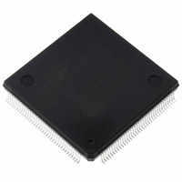
ST10F269Z2Q3 STMicroelectronics, ST10F269Z2Q3 Datasheet - Page 2

ST10F269Z2Q3
Manufacturer Part Number
ST10F269Z2Q3
Description
IC FLASH MEM 256KBIT 144-PQFP
Manufacturer
STMicroelectronics
Series
ST10r
Datasheet
1.ST10F269Z2Q3.pdf
(184 pages)
Specifications of ST10F269Z2Q3
Core Processor
ST10
Core Size
16-Bit
Speed
40MHz
Connectivity
CAN, EBI/EMI, SSC, UART/USART
Peripherals
POR, PWM, WDT
Number Of I /o
111
Program Memory Size
256KB (256K x 8)
Program Memory Type
FLASH
Ram Size
12K x 8
Voltage - Supply (vcc/vdd)
4.5 V ~ 5.5 V
Data Converters
A/D 16x10b
Oscillator Type
Internal
Operating Temperature
-40°C ~ 125°C
Package / Case
144-QFP
Processor Series
ST10F26x
Core
ST10
Data Bus Width
16 bit
Data Ram Size
12 KB
Interface Type
CAN, SSC, USART
Maximum Clock Frequency
40 MHz
Number Of Programmable I/os
111
Number Of Timers
2 x 16 bit
Operating Supply Voltage
0.3 V to 4 V
Maximum Operating Temperature
+ 125 C
Mounting Style
SMD/SMT
Minimum Operating Temperature
- 40 C
On-chip Adc
16 bit x 10 bit
Cpu Family
ST10
Device Core Size
16b
Frequency (max)
40MHz
Total Internal Ram Size
12KB
# I/os (max)
111
Number Of Timers - General Purpose
5
Operating Supply Voltage (typ)
5V
Operating Supply Voltage (max)
5.5V
Operating Supply Voltage (min)
4.5V
Instruction Set Architecture
CISC/RISC
Operating Temp Range
-40C to 125C
Operating Temperature Classification
Automotive
Mounting
Surface Mount
Pin Count
144
Package Type
PQFP
Lead Free Status / RoHS Status
Lead free / RoHS Compliant
Eeprom Size
-
Lead Free Status / Rohs Status
Lead free / RoHS Compliant
Other names
497-2042
Available stocks
Company
Part Number
Manufacturer
Quantity
Price
Company:
Part Number:
ST10F269Z2Q3
Manufacturer:
INFINEON
Quantity:
1 443
Company:
Part Number:
ST10F269Z2Q3
Manufacturer:
STMicroelectronics
Quantity:
10 000
Part Number:
ST10F269Z2Q3
Manufacturer:
ST
Quantity:
20 000
TABLE OF CONTENTS
ST10F269
1 -
2 -
3 -
4 -
5 -
6 -
7 -
8 -
2/184
Introduction ................................................................................................................. 6
Pin Data ...................................................................................................................... 7
Functional Description .............................................................................................. 13
Memory Organization ............................................................................................... 14
Internal Flash Memory .............................................................................................. 17
5.1 -
5.2 -
5.3 -
5.4 -
5.5 -
5.6 -
Central Processing Unit (CPU) ................................................................................. 35
6.1 -
6.2 -
6.3 -
External Bus Controller ............................................................................................. 43
7.1 -
7.2 -
Interrupt System ....................................................................................................... 45
8.1 -
8.2 -
8.3 -
OVERVIEW ................................................................................................................... 17
OPERATIONAL OVERVIEW ........................................................................................ 17
ARCHITECTURAL DESCRIPTION .............................................................................. 19
5.3.1 -
5.3.2 -
5.3.3 -
5.3.4 -
5.3.5 -
5.3.6 -
5.3.7 -
FLASH MEMORY CONFIGURATION .......................................................................... 26
APPLICATION EXAMPLES .......................................................................................... 26
5.5.1 -
5.5.2 -
5.5.3 -
BOOTSTRAP LOADER
5.6.1 -
5.6.2 -
5.6.3 -
5.6.4 -
5.6.5 -
MULTIPLIER-ACCUMULATOR UNIT (MAC) ............................................................... 36
6.1.1 -
INSTRUCTION SET SUMMARY .................................................................................. 38
MAC COPROCESSOR SPECIFIC INSTRUCTIONS ................................................... 39
PROGRAMMABLE CHIP SELECT TIMING CONTROL ............................................... 43
READY PROGRAMMABLE POLARITY ....................................................................... 43
EXTERNAL INTERRUPTS ........................................................................................... 45
INTERRUPT REGISTERS AND VECTORS LOCATION LIST ..................................... 46
INTERRUPT CONTROL REGISTERS ......................................................................... 47
Read Mode .................................................................................................... 19
Command Mode ............................................................................................ 19
Ready/Busy Signal ........................................................................................ 19
Flash Status Register .................................................................................... 19
Flash Protection Register .............................................................................. 21
Instructions Description ................................................................................. 21
Reset Processing and Initial State ................................................................ 26
Handling of Flash Addresses ........................................................................ 26
Basic Flash Access Control ........................................................................... 27
Programming Examples ................................................................................ 28
Entering the Bootstrap Loader ...................................................................... 31
Memory Configuration After Reset ................................................................ 32
Loading the Startup Code ............................................................................. 33
Exiting Bootstrap Loader Mode ..................................................................... 33
Choosing the Baud Rate for the BSL ............................................................ 34
Features ........................................................................................................ 37
6.1.1.1 -Enhanced Addressing Capabilities .................................................. 37
6.1.1.2 -Multiply-Accumulate Unit.................................................................. 37
6.1.1.3 -Program Control............................................................................... 37
.............................................................................................. 31
ST10F269
PAGE


