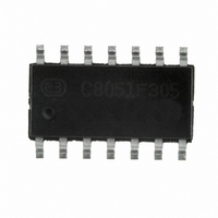
C8051F305-GS Silicon Laboratories Inc, C8051F305-GS Datasheet - Page 120

C8051F305-GS
Manufacturer Part Number
C8051F305-GS
Description
IC 8051 MCU 2K FLASH 14-SOIC
Manufacturer
Silicon Laboratories Inc
Series
C8051F30xr
Specifications of C8051F305-GS
Program Memory Type
FLASH
Program Memory Size
2KB (2K x 8)
Package / Case
14-SOIC (3.9mm Width), 14-SOL
Core Processor
8051
Core Size
8-Bit
Speed
25MHz
Connectivity
SMBus (2-Wire/I²C), UART/USART
Peripherals
POR, PWM, WDT
Number Of I /o
8
Ram Size
256 x 8
Voltage - Supply (vcc/vdd)
2.7 V ~ 3.6 V
Oscillator Type
External
Operating Temperature
-40°C ~ 85°C
Processor Series
C8051F3x
Core
8051
Data Bus Width
8 bit
Data Ram Size
256 B
Interface Type
I2C/SMBus/UART
Maximum Clock Frequency
25 MHz
Number Of Programmable I/os
8
Number Of Timers
3
Maximum Operating Temperature
+ 85 C
Mounting Style
SMD/SMT
3rd Party Development Tools
PK51, CA51, A51, ULINK2
Development Tools By Supplier
C8051F300DK
Minimum Operating Temperature
- 40 C
Lead Free Status / RoHS Status
Lead free / RoHS Compliant
For Use With
770-1006 - ISP 4PORT FOR SILABS C8051F MCU336-1444 - ADAPTER PROGRAM TOOLSTICK F300
Eeprom Size
-
Data Converters
-
Lead Free Status / Rohs Status
Lead free / RoHS Compliant
Other names
336-1540-5
C8051F300/1/2/3/4/5
120
Bit7:
Bit6:
Bit5:
Bit4:
Bit3:
Bit2:
Bit1:
Bit0:
MASTER TXMODE
Bit7
R
MASTER: SMBus Master/Slave Indicator.
This read-only bit indicates when the SMBus is operating as a master.
0: SMBus operating in Slave Mode.
1: SMBus operating in Master Mode.
TXMODE: SMBus Transmit Mode Indicator.
This read-only bit indicates when the SMBus is operating as a transmitter.
0: SMBus in Receiver Mode.
1: SMBus in Transmitter Mode.
STA: SMBus Start Flag.
Write:
0: No Start generated.
1: When operating as a master, a START condition is transmitted if the bus is free (If the bus
is not free, the START is transmitted after a STOP is received or a free timeout is detected).
If STA is set by software as an active Master, a repeated START will be generated after the
next ACK cycle.
Read:
0: No Start or repeated Start detected.
1: Start or repeated Start detected.
STO: SMBus Stop Flag.
Write:
As a master, setting this bit to ‘1’ causes a STOP condition to be transmitted after the next
ACK cycle. STO is cleared to ‘0’ by hardware when the STOP is generated.
As a slave, software manages this bit when switching from Slave Receiver to Slave Trans-
mitter mode. See
Read:
0: No Stop condition detected.
1: Stop condition detected (if in Slave Mode) or pending (if in Master Mode).
ACKRQ: SMBus Acknowledge Request.
This read-only bit is set to logic 1 when the SMBus has received a byte and needs the ACK
bit to be written with the correct ACK response value.
ARBLOST: SMBus Arbitration Lost Indicator.
This read-only bit is set to logic 1 when the SMBus loses arbitration while operating as a
transmitter. A lost arbitration while a slave indicates a bus error condition.
ACK: SMBus Acknowledge Flag.
This bit defines the outgoing ACK level and records incoming ACK levels. It should be writ-
ten each time a byte is received (when ACKRQ=1), or read after each byte is transmitted.
0: A "not acknowledge" has been received (if in Transmitter Mode) OR will be transmitted (if
in Receiver Mode).
1: An "acknowledge" has been received (if in Transmitter Mode) OR will be transmitted (if in
Receiver Mode).
SI: SMBus Interrupt Flag.
This bit is set by hardware under the conditions listed in Table 13.3. SI must be cleared by
software. While SI is set, SCL is held low and the SMBus is stalled.
Bit6
R
SFR Definition 13.2.
STA
R/W
Bit5
Section 13.5.4
STO
R/W
Bit4
for details.
ACKRQ ARBLOST
Rev. 2.9
SMB0CN: SMBus Control
Bit3
R
Bit2
R
ACK
R/W
Bit1
(bit addressable)
R/W
Bit0
SI
SFR Address:
00000000
Reset Value
0xC0


