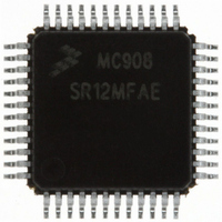
MC908SR12MFAE Freescale Semiconductor, MC908SR12MFAE Datasheet - Page 224

MC908SR12MFAE
Manufacturer Part Number
MC908SR12MFAE
Description
IC MCU 12K FLASH 8MHZ 48-LQFP
Manufacturer
Freescale Semiconductor
Series
HC08r
Datasheet
1.MC908SR12MFAE.pdf
(404 pages)
Specifications of MC908SR12MFAE
Core Processor
HC08
Core Size
8-Bit
Speed
8MHz
Connectivity
I²C, SCI
Peripherals
LVD, POR, PWM, Temp Sensor
Number Of I /o
31
Program Memory Size
12KB (12K x 8)
Program Memory Type
FLASH
Ram Size
512 x 8
Voltage - Supply (vcc/vdd)
4.5 V ~ 5.5 V
Data Converters
A/D 14x10b
Oscillator Type
Internal
Operating Temperature
-40°C ~ 125°C
Package / Case
48-LQFP
Lead Free Status / RoHS Status
Lead free / RoHS Compliant
Eeprom Size
-
Available stocks
Company
Part Number
Manufacturer
Quantity
Price
Company:
Part Number:
MC908SR12MFAE
Manufacturer:
Freescale Semiconductor
Quantity:
10 000
Company:
Part Number:
MC908SR12MFAER
Manufacturer:
Freescale Semiconductor
Quantity:
10 000
- Current page: 224 of 404
- Download datasheet (2Mb)
Analog Module
14.4.2 Two-Stage Amplifier
14.4.3 Amplifier Response Time
Data Sheet
224
The two-stage amplifier is used to amplify small input signals from the
on-chip temperature sensor or external voltage sources such as external
thermistor and current sensing resistor, for temperature and current
monitoring. The amplified signal, OPOUT, is fed to the ADC module for
analog-to-digital conversion. The gain of the two-stage amplifier is
defined by the GAINAx and GAINBx bits in the analog module gain
control register (AMGCR) (see
The two-stage amplifier requires the input signal to be stable for
sampling. This signal hold-time varies with gain setting for stage-1 of the
two-stage amplifier, and is determined by the formula:
The AMCLK clock is the analog amplifier clock, which is divided from the
ADC clock, ADCICLK.
The time for the two-stage amplifier to amplify the input signal to the
desired output is dependent on the gain setting in both stages of the two-
stage amplifier. The amplifier response time is determined by the
formula:
This amplifier response time should be added to the ADC conversion
time to obtain the total time for the small-signal conversion.
Therefore, conversion time for OPINx signals, with amplification is:
70 + (8 × Gain of stage-1) + (6 × Gain of stage-2) AMCLK cycles
10 + [(Gain of stage-1 amplifier – 1) × 2] AMCLK cycles
Amplifier response time + ADC conversion time
Analog Module
MC68HC908SR12•MC68HC08SR12 — Rev. 5.0
Figure
14-1).
Freescale Semiconductor
Related parts for MC908SR12MFAE
Image
Part Number
Description
Manufacturer
Datasheet
Request
R
Part Number:
Description:
Manufacturer:
Freescale Semiconductor, Inc
Datasheet:
Part Number:
Description:
Manufacturer:
Freescale Semiconductor, Inc
Datasheet:
Part Number:
Description:
Manufacturer:
Freescale Semiconductor, Inc
Datasheet:
Part Number:
Description:
Manufacturer:
Freescale Semiconductor, Inc
Datasheet:
Part Number:
Description:
Manufacturer:
Freescale Semiconductor, Inc
Datasheet:
Part Number:
Description:
Manufacturer:
Freescale Semiconductor, Inc
Datasheet:
Part Number:
Description:
Manufacturer:
Freescale Semiconductor, Inc
Datasheet:
Part Number:
Description:
Manufacturer:
Freescale Semiconductor, Inc
Datasheet:
Part Number:
Description:
Manufacturer:
Freescale Semiconductor, Inc
Datasheet:
Part Number:
Description:
Manufacturer:
Freescale Semiconductor, Inc
Datasheet:
Part Number:
Description:
Manufacturer:
Freescale Semiconductor, Inc
Datasheet:
Part Number:
Description:
Manufacturer:
Freescale Semiconductor, Inc
Datasheet:
Part Number:
Description:
Manufacturer:
Freescale Semiconductor, Inc
Datasheet:
Part Number:
Description:
Manufacturer:
Freescale Semiconductor, Inc
Datasheet:
Part Number:
Description:
Manufacturer:
Freescale Semiconductor, Inc
Datasheet:


