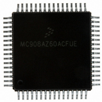
MC908AZ60ACFUE Freescale Semiconductor, MC908AZ60ACFUE Datasheet - Page 367

MC908AZ60ACFUE
Manufacturer Part Number
MC908AZ60ACFUE
Description
IC MCU FLASH 8.4MHZ 60K 64QFP
Manufacturer
Freescale Semiconductor
Series
HC08r
Datasheet
1.MC908AZ60ACFUER.pdf
(414 pages)
Specifications of MC908AZ60ACFUE
Core Processor
HC08
Core Size
8-Bit
Speed
8.4MHz
Connectivity
CAN, SCI, SPI
Peripherals
LVD, POR, PWM
Number Of I /o
52
Program Memory Size
60KB (60K x 8)
Program Memory Type
FLASH
Eeprom Size
1K x 8
Ram Size
2K x 8
Voltage - Supply (vcc/vdd)
4.5 V ~ 5.5 V
Data Converters
A/D 15x8b
Oscillator Type
Internal
Operating Temperature
-40°C ~ 85°C
Package / Case
64-QFP
Lead Free Status / RoHS Status
Lead free / RoHS Compliant
Available stocks
Company
Part Number
Manufacturer
Quantity
Price
Company:
Part Number:
MC908AZ60ACFUE
Manufacturer:
Freescale Semiconductor
Quantity:
10 000
Part Number:
MC908AZ60ACFUE
Manufacturer:
FREESCALE
Quantity:
20 000
Company:
Part Number:
MC908AZ60ACFUE1L87J
Manufacturer:
TEMIC
Quantity:
350
Company:
Part Number:
MC908AZ60ACFUER
Manufacturer:
FREESCALE
Quantity:
5 560
Company:
Part Number:
MC908AZ60ACFUER
Manufacturer:
Freescale Semiconductor
Quantity:
10 000
- Current page: 367 of 414
- Download datasheet (5Mb)
28.1.4 5.0 Volt DC Electrical Characteristics
1. V
2. Run (Operating) I
3. Wait I
4. Stop I
5. Although I
6. Maximum is highest voltage that POR is guaranteed.
7. Maximum is highest voltage that POR is possible.
8. If minimum V
9. See
10. See Monitor mode description within
Freescale Semiconductor
Output High Voltage
Total source current
Output Low Voltage
Total sink current
Input High Voltage
Input Low Voltage
V
I/O Ports Hi-Z Leakage Current
Input Current
Capacitance
Low-Voltage Reset Inhibit
POR ReArm Voltage
POR Reset Voltage
POR Rise Time Ramp Rate
High COP Disable Voltage
Monitor mode entry voltage on IRQ
Pull resistor (KBD[4:0])
100 pF on all outputs. C
modules enabled. Typical values at midpoint of voltage range, 25°C only.
all outputs, C
enabled. Typical values at midpoint of voltage range, 25°C only.
DD
Run
Wait
Stop
Ports (As Input or Output)
DD
(I
(I
(I
(I
All Ports, IRQs, RST, OSC1
All Ports, IRQs, RST, OSC1
LVI enabled, T
LVI disabled, T
LVI enabled, –40°C to +125°C
LVI disabled, –40°C to +125°C
Supply Current
15.8 COP Module During Break
LOAD
LOAD
LOAD
LOAD
= 5.0 Vdc ± 10%, V
DD
(2)
DD
(4)
(3)
measured using external square wave clock source (f
measured with OSC1 = V
DD
= –2.0 mA) All Ports
= –5.0 mA) All Ports
= 1.6 mA) All Ports
= 10.0 mA) All Ports
DD
L
is proportional to bus frequency, a current of several mA is present even at very low frequencies.
= 20 pF on OSC2. All ports configured as inputs. OSC2 capacitance linearly affects wait I
is not reached before the internal POR reset is released, RST must be driven low externally until minimum V
DD
A
A
measured using external square wave clock source (f
MC68HC908AZ60A • MC68HC908AS60A • MC68HC908AS60E Data Sheet, Rev. 6
= 25°C
(7)
= 25°C
(6)
Characteristic
SS
L
= 20 pF on OSC2. All ports configured as inputs. OSC2 capacitance linearly affects run I
= 0 Vdc, T
(9)
(8)
SS
.
Interrupts. V
A
Chapter 15 Computer Operating Properly
(10)
= –40°C to +T
(1)
HI
applied to RST.
A
(MAX), unless otherwise noted.
(recover)
(trip)
BUS
= 8.4 MHz). All inputs 0.2 Vdc from rail. No dc loads. Less than 100 pF on
I
I
V
Symbol
OH
OL
BUS
PORRST
R
I
C
V
V
DD
R
V
V
V
C
V
V
V
(TOT)
(TOT)
I
POR
POR
OUT
I
OH
IN
OL
LVI
PU
IH
L
IN
HI
HI
IL
(5)
= 8.4 MHz). All inputs 0.2 V from rail. No dc loads. Less than
(COP). V
V
V
0.7 x V
V
V
DD
DD
HI
DD
DD
3.80
0.02
Min
V
–1
–1
—
—
—
—
—
—
—
—
—
—
—
—
—
—
applied to IRQ or RST
0
0
SS
+ 3.0
+ 3.0
–0.8
–1.5
DD
Typical
DD
100
100
25
14
35
—
—
—
—
—
—
—
—
—
—
—
—
—
—
—
—
—
—
. Measured with all modules
Electrical Specifications
DD
V
V
0.3 x V
. Measured with all
DD
DD
Max
4.49
V
400
500
100
200
800
0.4
1.5
10
15
35
20
50
12
—
—
—
—
—
1
1
8
DD
+ 4.5
+ 4.5
DD
DD
is reached.
V/ms
Unit
mA
mA
mA
mA
mV
mV
μA
μA
μA
μA
μA
μA
pF
kΩ
V
V
V
V
V
V
V
367
Related parts for MC908AZ60ACFUE
Image
Part Number
Description
Manufacturer
Datasheet
Request
R
Part Number:
Description:
Manufacturer:
Freescale Semiconductor, Inc
Datasheet:
Part Number:
Description:
Manufacturer:
Freescale Semiconductor, Inc
Datasheet:
Part Number:
Description:
Manufacturer:
Freescale Semiconductor, Inc
Datasheet:
Part Number:
Description:
Manufacturer:
Freescale Semiconductor, Inc
Datasheet:
Part Number:
Description:
Manufacturer:
Freescale Semiconductor, Inc
Datasheet:
Part Number:
Description:
Manufacturer:
Freescale Semiconductor, Inc
Datasheet:
Part Number:
Description:
Manufacturer:
Freescale Semiconductor, Inc
Datasheet:
Part Number:
Description:
Manufacturer:
Freescale Semiconductor, Inc
Datasheet:
Part Number:
Description:
Manufacturer:
Freescale Semiconductor, Inc
Datasheet:
Part Number:
Description:
Manufacturer:
Freescale Semiconductor, Inc
Datasheet:
Part Number:
Description:
Manufacturer:
Freescale Semiconductor, Inc
Datasheet:
Part Number:
Description:
Manufacturer:
Freescale Semiconductor, Inc
Datasheet:
Part Number:
Description:
Manufacturer:
Freescale Semiconductor, Inc
Datasheet:
Part Number:
Description:
Manufacturer:
Freescale Semiconductor, Inc
Datasheet:
Part Number:
Description:
Manufacturer:
Freescale Semiconductor, Inc
Datasheet:


