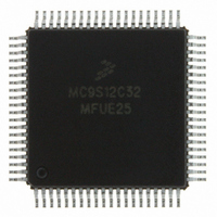
MC9S12C32MFUE25 Freescale Semiconductor, MC9S12C32MFUE25 Datasheet - Page 218

MC9S12C32MFUE25
Manufacturer Part Number
MC9S12C32MFUE25
Description
IC MCU 32K FLASH 25MHZ 80-QFP
Manufacturer
Freescale Semiconductor
Series
HCS12r
Datasheets
1.MC9S12GC16MFUE.pdf
(690 pages)
2.MC9S12C96CFUER.pdf
(26 pages)
3.MC9S12C32CFAE25.pdf
(2 pages)
Specifications of MC9S12C32MFUE25
Core Processor
HCS12
Core Size
16-Bit
Speed
25MHz
Connectivity
CAN, EBI/EMI, SCI, SPI
Peripherals
POR, PWM, WDT
Number Of I /o
60
Program Memory Size
32KB (32K x 8)
Program Memory Type
FLASH
Ram Size
2K x 8
Voltage - Supply (vcc/vdd)
2.35 V ~ 5.5 V
Data Converters
A/D 8x10b
Oscillator Type
Internal
Operating Temperature
-40°C ~ 125°C
Package / Case
80-QFP
Processor Series
S12C
Core
HCS12
Data Bus Width
16 bit
Data Ram Size
2 KB
Interface Type
CAN/SCI/SPI
Maximum Clock Frequency
25 MHz
Number Of Programmable I/os
60
Number Of Timers
8
Operating Supply Voltage
3.3 V to 5.5 V
Maximum Operating Temperature
+ 125 C
Mounting Style
SMD/SMT
3rd Party Development Tools
EWHCS12
Development Tools By Supplier
M68EVB912C32EE
Minimum Operating Temperature
- 40 C
On-chip Adc
8-ch x 10-bit
For Use With
CML12C32SLK - KIT STUDENT LEARNING 16BIT HCS12
Lead Free Status / RoHS Status
Lead free / RoHS Compliant
Eeprom Size
-
Lead Free Status / Rohs Status
Lead free / RoHS Compliant
Available stocks
Company
Part Number
Manufacturer
Quantity
Price
Company:
Part Number:
MC9S12C32MFUE25
Manufacturer:
Freescale Semiconductor
Quantity:
10 000
Part Number:
MC9S12C32MFUE25
Manufacturer:
FREESCALE
Quantity:
20 000
Company:
Part Number:
MC9S12C32MFUE25R
Manufacturer:
Freescale Semiconductor
Quantity:
10 000
- Current page: 218 of 690
- Download datasheet (4Mb)
Chapter 7 Debug Module (DBGV1) Block Description
7.4.2.5.8
In the inside range trigger mode, if the match condition for A and B happen on the same bus cycle, both
the A and B flags in DBGSC are set and a trigger occurs. If a match condition on only A or only B occurs
no flags are set. If TRGSEL = 1, the inside range is accurate only to word boundaries. If TRGSEL = 0, an
aligned word access which straddles the range boundary will cause a trigger only if the aligned address is
within the range.
7.4.2.5.9
In the outside range trigger mode, if the match condition for A or B is met, the corresponding flag in
DBGSC is set and a trigger occurs. If TRGSEL = 1, the outside range is accurate only to word boundaries.
If TRGSEL = 0, an aligned word access which straddles the range boundary will cause a trigger only if the
aligned address is outside the range.
7.4.2.5.10
The definitions of some of the control bits are incompatible with each other.
associated with it summarize how these incompatibilities are managed:
218
•
•
•
Read/write comparisons are not compatible with TRGSEL = 1. Therefore, RWAEN and RWBEN
are ignored.
Event-only trigger modes are always considered a begin-type trigger. See
“Storing with
Detail capture mode has priority over the event-only trigger/capture modes. Therefore, event-only
modes have no meaning in detail mode and their functions default to similar trigger modes.
A only
A or B
A then B
Event-only B
A then event-only B
A and B (full mode)
A and not B (full mode)
Inside range
Outside range
1 — Ignored — same as force
2 — Ignored for comparator B
3 — Reduces to effectively “B only”
4 — Works same as A then B
5 — Reduces to effectively “A only” — B not compared
6 — Only accurate to word boundaries
Inside Range (A ≤ address ≤ B)
Outside Range (address < A or address > B)
Control Bit Priorities
Mode
Begin-Trigger,” and
Table 7-25. Resolution of Mode Conflicts
MC9S12C-Family / MC9S12GC-Family
Tag
Section 7.4.2.8.2, “Storing with
1
2
5
6
6
5
Normal / Loop1
Rev 01.24
Force
Tag
1, 3
4
5
5
6
6
End-Trigger.”
Table 7-25
Detail
Section 7.4.2.8.1,
Freescale Semiconductor
Force
and the notes
3
4
Related parts for MC9S12C32MFUE25
Image
Part Number
Description
Manufacturer
Datasheet
Request
R
Part Number:
Description:
Manufacturer:
Freescale Semiconductor, Inc
Datasheet:
Part Number:
Description:
Manufacturer:
Freescale Semiconductor, Inc
Datasheet:
Part Number:
Description:
Manufacturer:
Freescale Semiconductor, Inc
Datasheet:
Part Number:
Description:
Manufacturer:
Freescale Semiconductor, Inc
Datasheet:
Part Number:
Description:
Manufacturer:
Freescale Semiconductor, Inc
Datasheet:
Part Number:
Description:
Manufacturer:
Freescale Semiconductor, Inc
Datasheet:
Part Number:
Description:
Manufacturer:
Freescale Semiconductor, Inc
Datasheet:
Part Number:
Description:
Manufacturer:
Freescale Semiconductor, Inc
Datasheet:
Part Number:
Description:
Manufacturer:
Freescale Semiconductor, Inc
Datasheet:
Part Number:
Description:
Manufacturer:
Freescale Semiconductor, Inc
Datasheet:
Part Number:
Description:
Manufacturer:
Freescale Semiconductor, Inc
Datasheet:
Part Number:
Description:
Manufacturer:
Freescale Semiconductor, Inc
Datasheet:
Part Number:
Description:
Manufacturer:
Freescale Semiconductor, Inc
Datasheet:
Part Number:
Description:
Manufacturer:
Freescale Semiconductor, Inc
Datasheet:
Part Number:
Description:
Manufacturer:
Freescale Semiconductor, Inc
Datasheet:


