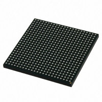
MCIMX512DJM8C Freescale Semiconductor, MCIMX512DJM8C Datasheet - Page 14

MCIMX512DJM8C
Manufacturer Part Number
MCIMX512DJM8C
Description
MULTIMEDIA PROC 529-LFBGA
Manufacturer
Freescale Semiconductor
Series
i.MX51r
Specifications of MCIMX512DJM8C
Core Processor
ARM Cortex-A8
Core Size
32-Bit
Speed
800MHz
Connectivity
1-Wire, EBI/EMI, Ethernet, I²C, IrDA, MMC, SPI, SSI, UART/USART, USB OTG
Peripherals
DMA, I²S, LCD, POR, PWM, WDT
Number Of I /o
128
Program Memory Type
ROMless
Ram Size
128K x 8
Voltage - Supply (vcc/vdd)
0.8 V ~ 1.15 V
Oscillator Type
External
Operating Temperature
-20°C ~ 85°C
Package / Case
529-LFBGA
Processor Series
i.MX51
Core
ARM Cortex A8
Data Bus Width
32 bit
Program Memory Size
36 KB
Data Ram Size
128 KB
Interface Type
I2C, SPI, SSI, UART, USB
Maximum Clock Frequency
200 MHz
Number Of Timers
5
Operating Supply Voltage
0.8 V to 1.15 V
Maximum Operating Temperature
+ 85 C
Mounting Style
SMD/SMT
3rd Party Development Tools
MDK-ARM, RL-ARM, ULINK2
Development Tools By Supplier
MCIMX51EVKJ
Minimum Operating Temperature
- 20 C
Lead Free Status / RoHS Status
Lead free / RoHS Compliant
Eeprom Size
-
Program Memory Size
-
Data Converters
-
Lead Free Status / Rohs Status
Lead free / RoHS Compliant
Available stocks
Company
Part Number
Manufacturer
Quantity
Price
Company:
Part Number:
MCIMX512DJM8C
Manufacturer:
Freescale Semiconductor
Quantity:
10 000
Part Number:
MCIMX512DJM8C
Manufacturer:
FREESCALE
Quantity:
20 000
IOMUX Configuration for Boot Media
3
The information provided in this section describes the contacts assigned for each type of bootable media.
It also includes data about the clocks used during boot flow and their frequencies. Signals that can be
multiplexed appear in tables throughout this section. See the IOMUXC chapter in the i.MX51 Multimedia
Applications Processor Reference Manual (MCIMX51RM) for details about how to program the IOMUX
controller.
14
VREG
XTAL/EXTAL
Signal Name
IOMUX Configuration for Boot Media
JTAG_TCK
JTAG_TMS
JTAG_TDI
JTAG_TDO
JTAG_TRSTB
JTAG_DE_B
JTAG_MOD
i.MX51 Applications Processors for Consumer and Industrial Products, Rev. 4
JTAG
This regulator is no longer used and should be floated by the user.
The user should tie a fundamental-mode crystal across XTAL and EXTAL. The crystal must be
rated for a maximum drive level of 100
80 Ω or less is recommended. Freescale BSP (Board Support Package) software requires 24 MHz
on EXTAL.
The crystal can be eliminated if an external 24 MHz oscillator is available. In this case, EXTAL must
be directly driven by the external oscillator and XTAL is floated. The EXTAL signal level must swing
from NVCC_OSC to GND. If the clock is used for USB, then there are strict jitter requirements:
< 50 ps peak-to-peak below 1.2 MHz and < 100 ps peak-to-peak above 1.2 MHz for the USB PHY.
The COSC_EN bit in the CCM (Clock Control Module) must be cleared to put the on-chip oscillator
circuit in bypass mode which allows EXTAL to be externally driven. COSC_EN is bit 12 in the CCR
register of the CCM.
Table 3. Special Signal Considerations (continued)
Table 4. JTAG Controller Interface Summary
Input/open-drain output
3-state output
I/O Type
Input
Input
Input
Input
Input
μ
W or higher. An ESR (equivalent series resistance) of
Remarks
On-chip Termination
100 kΩ pull-down
100 kΩ pull-down
47 kΩ pull-up
47 kΩ pull-up
47 kΩ pull-up
47 kΩ pull-up
Keeper
Freescale Semiconductor


